Signal Processing
The ladder wave generator circuit composed of the SN74163
Published:2011/8/26 2:14:00 Author:TaoXi | Keyword: ladder wave, generator | From:SeekIC

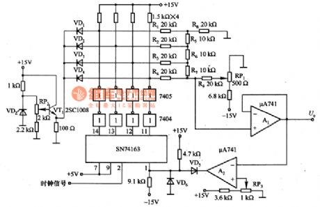
The ladder wave generator circuit composed of the SN74163 is as shown in the figure. In this circuit, the SN74163 is the synchronous counter which is the same as the clock, it can choose the frequency dividing ratio, so this device is very convenient. The VDZ and VT1 are the reference power supply that can supply the reference voltage to the D/A converter. The R1~R9 are the ladder-shaped D/A converter, it changes the input digital quantity into the analog voltage. The 7404 and 7405 are the buffer; A2 is the comparator; A1 is the outputbuffer, it outputs the step-wave voltage. RP1 is the step 1 regulation voltage; RP2 can be used to adjust the maximum voltage of the step; RP3 can be used to adjust the number of the step.
Reprinted Url Of This Article:
http://www.seekic.com/circuit_diagram/Signal_Processing/The_ladder_wave_generator_circuit_composed_of_the_SN74163.html
Print this Page | Comments | Reading(3)

Article Categories
power supply circuit
Amplifier Circuit
Basic Circuit
LED and Light Circuit
Sensor Circuit
Signal Processing
Electrical Equipment Circuit
Control Circuit
Remote Control Circuit
A/D-D/A Converter Circuit
Audio Circuit
Measuring and Test Circuit
Communication Circuit
Computer-Related Circuit
555 Circuit
Automotive Circuit
Repairing Circuit
Code: