Signal Processing
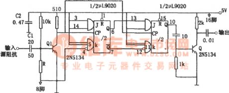
The frequency splitter of symmetric output waveforms (μL9020)
Published:2011/6/22 4:29:00 Author:Borg | Keyword: frequency splitter, symmetric output waveforms | From:SeekIC

The figured splitter circuit is triggered when the peak value is in the range of 0.5~5v, no matter whether it is the sine wave or the square wave. The working frequency of the circuit is 40MHz. The input signal of the frequency splitter drives the J-K triggers after it has passed the amplitude limit amplifier Q1, finally, it crosses the buffer Q2 and is output. The transistor Q1 offers the first stage splitter a proper triggering LEV. When the high LEV drives, the capacitor C1 plays a part of current limitation. If the drive LEV is low, we can expand the volume of C1, the the trigger power is increased.
Reprinted Url Of This Article:
http://www.seekic.com/circuit_diagram/Signal_Processing/The_frequency_splitter_of_symmetric_output_waveforms_μL9020.html
Print this Page | Comments | Reading(3)

Article Categories
power supply circuit
Amplifier Circuit
Basic Circuit
LED and Light Circuit
Sensor Circuit
Signal Processing
Electrical Equipment Circuit
Control Circuit
Remote Control Circuit
A/D-D/A Converter Circuit
Audio Circuit
Measuring and Test Circuit
Communication Circuit
Computer-Related Circuit
555 Circuit
Automotive Circuit
Repairing Circuit
Code: