Signal Processing
The digital frequency doubler(LM108 and LM111)
Published:2011/6/17 9:45:00 Author:Borg | Keyword: digital frequency doubler | From:SeekIC

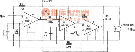
The circuit consists of the voltage comparator, Miller integrator and OR gate. A1 is the LEV comparator, which is fulfilled by the chip LM111, the chip forms the rectifier circuit that converts the long-rising-time waveform (such as the sine wave) to the short-rising-time square wave. The square wave output by A1 is turned into the triangular wave by the Miller integrator which consists of A2, R4 and C4, and then the LEV comparator A3 turns the triangular wave into the square wave. There is a 90⁰ phase difference between A1 and A3, so after crossing the the OR gate, the wave is doubled and then output.
Reprinted Url Of This Article:
http://www.seekic.com/circuit_diagram/Signal_Processing/The_digital_frequency_doublerLM108_and_LM111.html
Print this Page | Comments | Reading(3)

Article Categories
power supply circuit
Amplifier Circuit
Basic Circuit
LED and Light Circuit
Sensor Circuit
Signal Processing
Electrical Equipment Circuit
Control Circuit
Remote Control Circuit
A/D-D/A Converter Circuit
Audio Circuit
Measuring and Test Circuit
Communication Circuit
Computer-Related Circuit
555 Circuit
Automotive Circuit
Repairing Circuit
Code: