Signal Processing
The auto detecting and heating circuit of 555 minimum temperature
Published:2011/5/29 20:53:00 Author:Borg | Keyword: detecting and heating circuit, minimum temperature | From:SeekIC

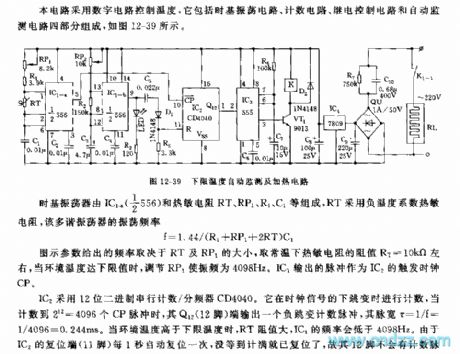
The circuit controls temperature in a digital way, which includes four sub-circuits, they are time-base oscillation circuit, counting circuit, relay control circuit and auto monitoring circuit, see as Figure 12-39.
Figure 12-39 The auto detecting and heating circuit of the minimum temperature The time-based oscillator consists of IC1-4(1/2*556) and thermistor of RT1,RP1,R1 and C1,etc, RT is made of negative temperature coefficient thermistors, and the frequency of the multi-resonate oscillator is:
f=1.44/(R1+RP1+2RT)C1
The frequency of the parameter in the figure depends on RT and RP1,and the selected resistance of the thermistor is about RT=10KΩ.
Reprinted Url Of This Article:
http://www.seekic.com/circuit_diagram/Signal_Processing/The_auto_detecting_and_heating_circuit_of_555_minimum_temperature.html
Print this Page | Comments | Reading(3)

Article Categories
power supply circuit
Amplifier Circuit
Basic Circuit
LED and Light Circuit
Sensor Circuit
Signal Processing
Electrical Equipment Circuit
Control Circuit
Remote Control Circuit
A/D-D/A Converter Circuit
Audio Circuit
Measuring and Test Circuit
Communication Circuit
Computer-Related Circuit
555 Circuit
Automotive Circuit
Repairing Circuit
Code: