Signal Processing
The auto-control circuit of 555 ventilators
Published:2011/5/27 20:46:00 Author:Borg | Keyword: auto-control circuit, 555 ventilators | From:SeekIC

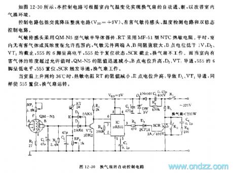
See as Figure 12-30, the control circuit can fulfill the auto on/off of the ventilator, so that the interior air temperature can be improved. The control circuit includes the AC step-down rectifier circuit(), harmful gas sensor, temperature test circuit and dual steady control circuit. The air sensor is made of QM-N5 gas-sensitive elements, and RT is fixed with the MF-51 NTC thermistor. Usually, when the harmful gas or it content is in the permissible range, the resistance between the two terminals A and B of the gas-sensitive sensor is high, and the LEV of B terminal is lower than 1V.
Reprinted Url Of This Article:
http://www.seekic.com/circuit_diagram/Signal_Processing/The_auto_control_circuit_of_555_ventilators.html
Print this Page | Comments | Reading(3)

Article Categories
power supply circuit
Amplifier Circuit
Basic Circuit
LED and Light Circuit
Sensor Circuit
Signal Processing
Electrical Equipment Circuit
Control Circuit
Remote Control Circuit
A/D-D/A Converter Circuit
Audio Circuit
Measuring and Test Circuit
Communication Circuit
Computer-Related Circuit
555 Circuit
Automotive Circuit
Repairing Circuit
Code: