Signal Processing
The 555 wind speed controller circuit
Published:2011/5/27 21:51:00 Author:Borg | Keyword: wind speed controller | From:SeekIC

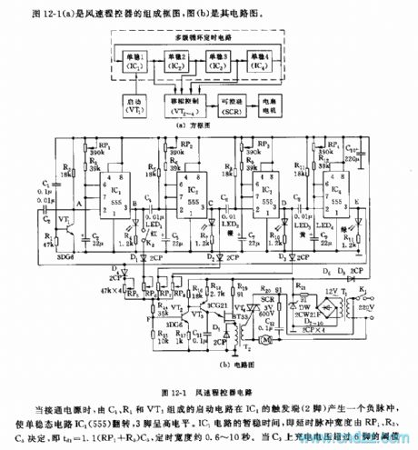
Figure 12-1(a) is a combination circuit of wind speed controller, and (b) is a another circuitWhen the power is getting through, the starting circuit consisting of C1, R1 and VT1 generates a negative pulse on the trigger terminal(2-lead) of IC1, which reverses the single steady circuit of IC1(555), and the 3-lead is in a high LEV. The temporarily steady time of IC1, i.e the pulse width of time delay, is decided by RP1,R2 and C3, i.e td=1.1(RP1+R3)C3, the timing width is about 0.6~10s. When the charging voltage on C3 is higher than the 6-pin threshold value LEV of 2/3VDD, the trigger is reset, and 3-pin is in a low LEV.
Reprinted Url Of This Article:
http://www.seekic.com/circuit_diagram/Signal_Processing/The_555_wind_speed_controller_circuit.html
Print this Page | Comments | Reading(3)

Article Categories
power supply circuit
Amplifier Circuit
Basic Circuit
LED and Light Circuit
Sensor Circuit
Signal Processing
Electrical Equipment Circuit
Control Circuit
Remote Control Circuit
A/D-D/A Converter Circuit
Audio Circuit
Measuring and Test Circuit
Communication Circuit
Computer-Related Circuit
555 Circuit
Automotive Circuit
Repairing Circuit
Code: