Signal Processing
The 555 timer circuit of independent adjustable on/off timing
Published:2011/5/30 20:52:00 Author:Borg | Keyword: timer circuit, adjustable | From:SeekIC

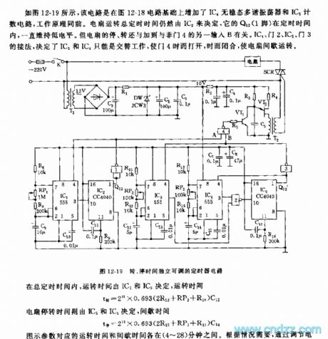
See as Figure 12-19, the circuit is added with a IC4 non-steady multi-resonate oscillator and IC5 counting circuit on the base of Figure 12-18, but the working principles are the same. The general timing of fan running is still decided by IC2 whose Q12 point (1-pin) remains in a low LEV during the time, but the switch of ON/OFF has something to do with another input B of NAND 4. The connection method of IC4, NAND 2, IC5 and NAND 3 decides that IC3 and IC4 can only work in turn, which makes the NAND 4 open and close now and than, and the fan runs intermittently.
Reprinted Url Of This Article:
http://www.seekic.com/circuit_diagram/Signal_Processing/The_555_timer_circuit_of_independent_adjustable_on_off_timing.html
Print this Page | Comments | Reading(3)

Article Categories
power supply circuit
Amplifier Circuit
Basic Circuit
LED and Light Circuit
Sensor Circuit
Signal Processing
Electrical Equipment Circuit
Control Circuit
Remote Control Circuit
A/D-D/A Converter Circuit
Audio Circuit
Measuring and Test Circuit
Communication Circuit
Computer-Related Circuit
555 Circuit
Automotive Circuit
Repairing Circuit
Code: