Signal Processing
The 555 pulse electric therapeutic apparatus circuit
Published:2011/6/27 22:11:00 Author:Borg | Keyword: pulse, electric therapeutic apparatus | From:SeekIC

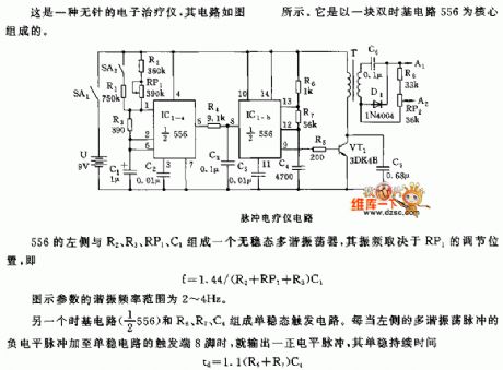
This is the stingless electric therapeutic apparatus, whose circuit is shown in the figure. It is formed based on a dual time-based circuit 556.
The pulse electric therapeutic apparatus circuit The left side of 555 composes an astable multi-resonance oscillator with R2, R3, RP1 and C1, whose oscillating frequency is decided by the position of RP1, i.e:F=1.44/(R2+RP1+R3)C1 The resonance frequency of the figured parameter is 2~4Hz. Another time-base circuit (1/2 556) composes a single stable trigger circuit. Once the passive LEV pulse of the resonance oscillating pulses on the left side is added on the 8-pin of the trigger terminal of the single steady circuit, a positive LEV pulse is output.
Reprinted Url Of This Article:
http://www.seekic.com/circuit_diagram/Signal_Processing/The_555_pulse_electric_therapeutic_apparatus_circuit.html
Print this Page | Comments | Reading(3)

Article Categories
power supply circuit
Amplifier Circuit
Basic Circuit
LED and Light Circuit
Sensor Circuit
Signal Processing
Electrical Equipment Circuit
Control Circuit
Remote Control Circuit
A/D-D/A Converter Circuit
Audio Circuit
Measuring and Test Circuit
Communication Circuit
Computer-Related Circuit
555 Circuit
Automotive Circuit
Repairing Circuit
Code: