Signal Processing
The 555 breeze ceiling fan timer circuit
Published:2011/5/28 20:14:00 Author:Borg | Keyword: ceiling fan, timer circuit | From:SeekIC

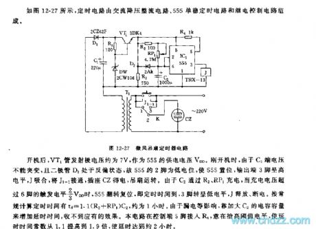
See as Figure 12-27, the timing circuit consists of step-down rectifier circuit, 555 single steady timing circuit and relay control circuit.
Figure 12-27 the breeze ceiling fan timer circuitAfter the fan has started, the voltage on injection pole of VT1 pipe is about 7v, which is the power supply voltage of 555. And when it is starting, since the voltage on C2 can not be changed suddenly, and the diode of D2 is in a reverse bias state, so the 2-pin of 555 is in a low LEV which makes 555 offset, the 3-pin is in a high LEV, J pulls in and J1-1 is getting through, the outlet of CZ gets power and the fan runs.
Reprinted Url Of This Article:
http://www.seekic.com/circuit_diagram/Signal_Processing/The_555_breeze_ceiling_fan_timer_circuit.html
Print this Page | Comments | Reading(3)

Article Categories
power supply circuit
Amplifier Circuit
Basic Circuit
LED and Light Circuit
Sensor Circuit
Signal Processing
Electrical Equipment Circuit
Control Circuit
Remote Control Circuit
A/D-D/A Converter Circuit
Audio Circuit
Measuring and Test Circuit
Communication Circuit
Computer-Related Circuit
555 Circuit
Automotive Circuit
Repairing Circuit
Code: