Signal Processing
The 555 analog natural wind circuit(3)
Published:2011/5/30 21:38:00 Author:Borg | Keyword: natural wind | From:SeekIC

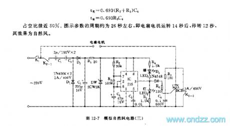
See as Figure 12-7, the circuit includes a capacitor step-down rectifier circuit, 555 multi-resonate oscillator and controllable silicon control circuit.The rectifier circuit generates a LEV of +7V as the power supply of 555. IC, R2,R3 and C4 consist a non-steady multi-resonate oscillator, whose frequency is T=0.693(R2+2R3)C4, of whichT(light)=0.693(R2+R3)C4T(discharging)=0.693R3C4The duty cycle is close to 50%. The period of the figure parameter is about 26S, i.e after the fan motor runs for about 14s, it stops and keeps still for 12s, the effect is the natural wind.
Figure 12-7 the analog natural wind circuit(3)
Reprinted Url Of This Article:
http://www.seekic.com/circuit_diagram/Signal_Processing/The_555_analog_natural_wind_circuit3.html
Print this Page | Comments | Reading(3)

Article Categories
power supply circuit
Amplifier Circuit
Basic Circuit
LED and Light Circuit
Sensor Circuit
Signal Processing
Electrical Equipment Circuit
Control Circuit
Remote Control Circuit
A/D-D/A Converter Circuit
Audio Circuit
Measuring and Test Circuit
Communication Circuit
Computer-Related Circuit
555 Circuit
Automotive Circuit
Repairing Circuit
Code: