Signal Processing
The 555 analog natural wind circuit(1)
Published:2011/5/30 21:26:00 Author:Borg | Keyword: natural wind | From:SeekIC

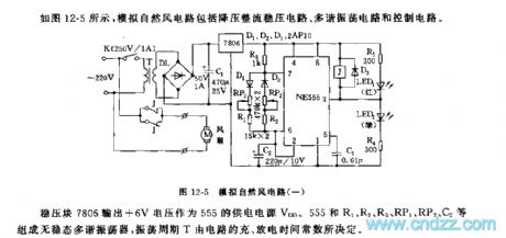
See as Figure 12-5, the analog natural circuit includes a step-down rectifier circuit, multi-resonate oscillating circuit and control circuit.
The oscillating period and the duty cycle of the pulse square wave can be changed by adjusting RP1 and RP2. As D1 and D2 are linked in the charging and discharging circuits respectively, the charging time and discharging time can be adjusted separately. At the beginning of power-on, since the voltage on C2 can not mutate, the 2-pin of 555 is like a grounded connection LEV, and 3-pin is in a high LEV, the relay is still, the normally closed contact makes the fan get power,rotate and launch winds.
Reprinted Url Of This Article:
http://www.seekic.com/circuit_diagram/Signal_Processing/The_555_analog_natural_wind_circuit1.html
Print this Page | Comments | Reading(3)

Article Categories
power supply circuit
Amplifier Circuit
Basic Circuit
LED and Light Circuit
Sensor Circuit
Signal Processing
Electrical Equipment Circuit
Control Circuit
Remote Control Circuit
A/D-D/A Converter Circuit
Audio Circuit
Measuring and Test Circuit
Communication Circuit
Computer-Related Circuit
555 Circuit
Automotive Circuit
Repairing Circuit
Code: