Signal Processing
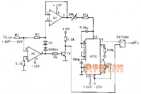
Signal repeater circuit schematic
Published:2014/4/16 20:40:00 Author:lynne | Keyword: Signal repeater circuit schematic, RC4558 | From:SeekIC

Illustrates the use of two operational amplifiers constituting the signal and a frequency-voltage converter A1.A2 transfer circuit 4153, the input signal UF amplitude varies between -10 ~-10V, the output signal UA, issued by the exclusive or gate. A1.A2 op amp can be used RC4558 or other models can be used 2N222 transistor VT1 or similar model, resistor R1 (10Ω) accuracy class shall be of ± 0.1%. As shown in Figure transponder signal circuit schematics:
Reprinted Url Of This Article:
http://www.seekic.com/circuit_diagram/Signal_Processing/Signal_repeater_circuit_schematic.html
Print this Page | Comments | Reading(3)

Article Categories
power supply circuit
Amplifier Circuit
Basic Circuit
LED and Light Circuit
Sensor Circuit
Signal Processing
Electrical Equipment Circuit
Control Circuit
Remote Control Circuit
A/D-D/A Converter Circuit
Audio Circuit
Measuring and Test Circuit
Communication Circuit
Computer-Related Circuit
555 Circuit
Automotive Circuit
Repairing Circuit
Code: