Signal Processing
Signal Circuit of Duty Ratio Ajustable Clock Consisting of 4 NAND gates
Published:2011/5/7 7:30:00 Author:Joyce | Keyword: Signal, Duty Ratio Ajustable, Clock , Consisting of 4 NAND gates | From:SeekIC
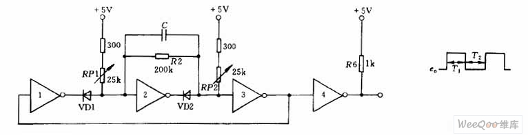
As shown in graph, the circuit is composedof four NAND gates. Oscillation signal frequency is decided by C and the value of potentiometer RP1. RP2 . Changing the resistance of potentiometer can change the frequency whose adjustment range can be 20:1.The resistance of potentiometer RP2 sets the width of output waveform T1 ,and the resistance of potentiometer RP2 sets the width of the output waveform T2.
Reprinted Url Of This Article:
http://www.seekic.com/circuit_diagram/Signal_Processing/Signal_Circuit_of_Duty_Ratio_Ajustable_Clock_Consisting_of_4_NAND_gates.html
Print this Page | Comments | Reading(3)

Article Categories
power supply circuit
Amplifier Circuit
Basic Circuit
LED and Light Circuit
Sensor Circuit
Signal Processing
Electrical Equipment Circuit
Control Circuit
Remote Control Circuit
A/D-D/A Converter Circuit
Audio Circuit
Measuring and Test Circuit
Communication Circuit
Computer-Related Circuit
555 Circuit
Automotive Circuit
Repairing Circuit
Code: