Signal Processing
SINE_WAIF_GENERATOR
Published:2009/7/10 0:59:00 Author:May | From:SeekIC


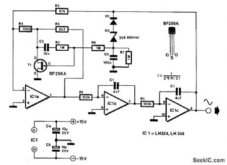
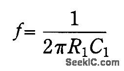
The frequency of the generator is determined by integrators IC1B and IC1C. An integrator has two properties that are used in this design. Firstly, a phase shift of 90° is between the input and output (ignor-ing, for the moment, the nonideal behavior of the op amp), and secondly, its amplification is - 1 (i.e., the signal inverts), provided the frequency:Cascading two identical integrators will thus result in an overall phase shift of 180° and an amplification of unity (provided that the frequency is1/2π/R1C1): an ideal basis for art oscillator. The two integrators are connected in the feedback circuit of an amplifier whose gain is determined by the amplitude of the output signal. Consequently, the generator has reasonably stable output voltage (at a level of about 4.5 Vpp).With the values of C1 (C1') and RI (R1'), as shown in the diagram, the output has a frequency of about 300 Hz. The frequency can be varied by replacing R1and R1' with a stereo potentiometer. To keep the frequency setting within bounds, the overall range of this potentiometer should not exceed a decade.The maximum attainable frequency is about 5 kHz. Distortion is not greater than 0.10/0. The current drawn by the generator is only a few milliamperes. Finally, the LM348 is a quadruple 741; it is thus possi-ble to construct the generator from four 741s.
Reprinted Url Of This Article:
http://www.seekic.com/circuit_diagram/Signal_Processing/SINE_WAIF_GENERATOR.html
Print this Page | Comments | Reading(3)

Article Categories
power supply circuit
Amplifier Circuit
Basic Circuit
LED and Light Circuit
Sensor Circuit
Signal Processing
Electrical Equipment Circuit
Control Circuit
Remote Control Circuit
A/D-D/A Converter Circuit
Audio Circuit
Measuring and Test Circuit
Communication Circuit
Computer-Related Circuit
555 Circuit
Automotive Circuit
Repairing Circuit
Code: