Signal Processing
SIMPLE_PLL_DEMODULATOR
Published:2009/7/16 2:11:00 Author:Jessie | From:SeekIC

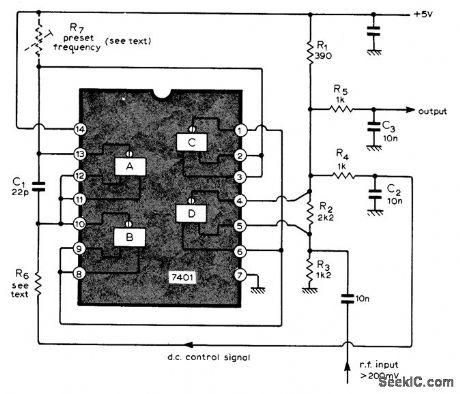
Requires only single IC to provide synchronous detection. Performance is satisfactory for most requirements of most amateur radio experimenters. Gates A, B, and C in IC form relaxation-type VCO whose output frequency is determined by C1 and positive current sources supplying pins 10 and 13 of IC. When pin 6 is high, gate D is biased by R2 and R3 to operate as linear amplifier for input signal. In operation, pin 6 is made alternately high and low by oscillator output, so D acts as amplifying phase detector. Output goes through low-pass filter R4-C2 to VCO, completing phase-locked loop. Separate filter R5-C3 provides AF output. When C1 is 22 pF, circuit operates at about 10 MHz. With 270 ohms for R6, lock is maintained over range of 2 MHz; with 10 kilohms, locking range is 300 kHz. R7 is optional, for fine adjustment of frequency.-R. King, Phase-Locked Loop Demodulator, Wireless World, July 1973, p 337.
Reprinted Url Of This Article:
http://www.seekic.com/circuit_diagram/Signal_Processing/SIMPLE_PLL_DEMODULATOR.html
Print this Page | Comments | Reading(3)

Article Categories
power supply circuit
Amplifier Circuit
Basic Circuit
LED and Light Circuit
Sensor Circuit
Signal Processing
Electrical Equipment Circuit
Control Circuit
Remote Control Circuit
A/D-D/A Converter Circuit
Audio Circuit
Measuring and Test Circuit
Communication Circuit
Computer-Related Circuit
555 Circuit
Automotive Circuit
Repairing Circuit
Code: