Signal Processing
SCA_RECEIVER
Published:2009/7/17 3:15:00 Author:Jessie | From:SeekIC

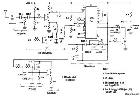
A simple PLL-based FM demodulator can be made to demodulate two subcarriers and provide a source of background music. The input to this receiver is fed from the wideband audio output from an FM radio's first FM detector. This is the point that feeds the FM stereo demodulator in an FM receiver. Care should be taken to ensure that the signal is tapped off at a point which hasn't yet been filtered [the subcarrier(s) are still present]. This FM input signal is then passed through a second-order high-pass filter and peaker stage (Q1), which serves to bandpass and provide additional gain within the input spectrum prior to the FM demodulator input. The FM detection is accomplished by a simple LM565 PLL IC (U1) operating as an FM demodulator. The PLL's VCO is tuned to 91 kHz via RT/CT. The demodulated output signal is available at pin 7, which is followed by a second-order LPF/buffer combination (Q4). The characteristics of this filter can be modified to suit the user. The design shown has an audio corner frequency of about 5 kHz. The filtered output is the recovered audio output and is the input to an audio amplifier. To choose the second subcarrier (67 kHz), the peaker and VCO are gang-tuned by the Q2 and Q3 saturating switch transistors. These devices switch in appropriate-valued parallel capacitors to retune the peaker and VCO to the proper frequency for reception of the second subcarrier signal. Circuit values shown are for an FM level of about 50 to 300 mV rms at the input to the peaker stage. In addition, the PLL dynamic characteristics can be altered as desired by modifying the loop filter. The typical recovered audio level at pin 7 of U1 is 200 mV rms. To receive SCA signals, the FM receiver can simply be tuned to normal FM stations, and then the presence of either or both subcarriers can be checked.
Reprinted Url Of This Article:
http://www.seekic.com/circuit_diagram/Signal_Processing/SCA_RECEIVER.html
Print this Page | Comments | Reading(3)

Article Categories
power supply circuit
Amplifier Circuit
Basic Circuit
LED and Light Circuit
Sensor Circuit
Signal Processing
Electrical Equipment Circuit
Control Circuit
Remote Control Circuit
A/D-D/A Converter Circuit
Audio Circuit
Measuring and Test Circuit
Communication Circuit
Computer-Related Circuit
555 Circuit
Automotive Circuit
Repairing Circuit
Code: