Signal Processing
REDUCING_RIPPLE_IN_A_SWITCHING_VOLTAGE_REGULATOR
Published:2009/6/24 5:17:00 Author:May | From:SeekIC
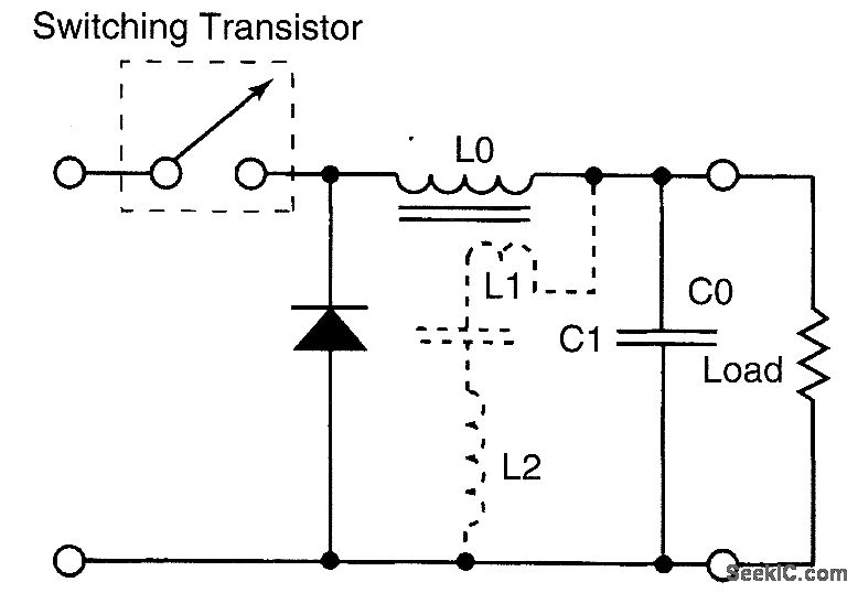
Simple additional circuitry that consists of relatively small components can reduce the output ripple by a factor of about 10. The additional components are indicated by the dashed lines.A current opposing the ripple is injected into the filter capacitor. The essence of the present technique is to inject, into this capacitor, a cur-rent opposite to that which already flows into this capacitor. A small additional winding, L1, in inductor L0 provides transformer coupling to generate the current that opposes the original ripple current. The circuit from L1 through C0 is completed by a small additional extemal inductor L2 and coupling capacitor C1.
Reprinted Url Of This Article:
http://www.seekic.com/circuit_diagram/Signal_Processing/REDUCING_RIPPLE_IN_A_SWITCHING_VOLTAGE_REGULATOR.html
Print this Page | Comments | Reading(3)

Article Categories
power supply circuit
Amplifier Circuit
Basic Circuit
LED and Light Circuit
Sensor Circuit
Signal Processing
Electrical Equipment Circuit
Control Circuit
Remote Control Circuit
A/D-D/A Converter Circuit
Audio Circuit
Measuring and Test Circuit
Communication Circuit
Computer-Related Circuit
555 Circuit
Automotive Circuit
Repairing Circuit
Code: