Signal Processing
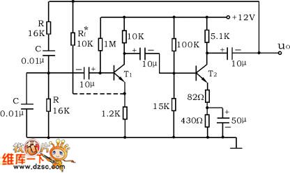
RC series-parallel frequency selection network oscillator circuit
Published:2011/6/4 23:39:00 Author:John | Keyword: frequency selection network | From:SeekIC


Disconnect the RC series-parallel network to measure amplifier’s quiescent point and its voltage gain.
Disconnect the RC series-parallel network and the amplifier. Apply the sinusoidal signal of the function signal generator into the RC series-parallel network. Keep the signal amplitude still (about 3V). The frequency changes from low to high, so the output amplitude of RC series-parallel network would change. When the signal source reaches a certain frequency, the output of RC series-parallel network will reach the maximum value (about 1V). And when the input and output are with the phase, the signal source frequency is .
Reprinted Url Of This Article:
http://www.seekic.com/circuit_diagram/Signal_Processing/RC_series_parallel_frequency_selection_network_oscillator_circuit.html
Print this Page | Comments | Reading(3)

Article Categories
power supply circuit
Amplifier Circuit
Basic Circuit
LED and Light Circuit
Sensor Circuit
Signal Processing
Electrical Equipment Circuit
Control Circuit
Remote Control Circuit
A/D-D/A Converter Circuit
Audio Circuit
Measuring and Test Circuit
Communication Circuit
Computer-Related Circuit
555 Circuit
Automotive Circuit
Repairing Circuit
Code: