Signal Processing
Quartz_stabilized_bridge_oscillator
Published:2009/7/24 5:33:00 Author:Jessie | From:SeekIC

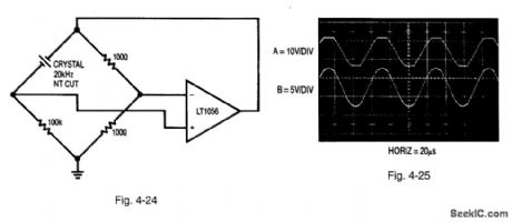
Figure 4-24 shows a bridge-based oscillator, where one leg of the bridge is replaced with a resonant element. Figure 4-25 shows the waveforms. With the crystal removed, the circuit is a basic non-inverting gain-of-two amplifier with grounded input. Inserting the crystal closes a positive-feedback path at the crystal resonant frequency. The amplifier output (trace A, Fig. 4-25) swings in an attempt to maintain input balance. Excessive circuit gain prevents linear operation, and oscillations start when the amplifier repeatedly overshoots in an attempt to null the bridge. The high Q of the crystal is evident in the filtered waveform (trace B) at the amplifier positive input. LINEAR TECHNOLOGY APPLICATION NOTE 43, P. 27.
Reprinted Url Of This Article:
http://www.seekic.com/circuit_diagram/Signal_Processing/Quartz_stabilized_bridge_oscillator.html
Print this Page | Comments | Reading(3)

Article Categories
power supply circuit
Amplifier Circuit
Basic Circuit
LED and Light Circuit
Sensor Circuit
Signal Processing
Electrical Equipment Circuit
Control Circuit
Remote Control Circuit
A/D-D/A Converter Circuit
Audio Circuit
Measuring and Test Circuit
Communication Circuit
Computer-Related Circuit
555 Circuit
Automotive Circuit
Repairing Circuit
Code: