Signal Processing
Pulse Test Set (the 3rd)
Published:2011/7/17 5:33:00 Author:Felicity | Keyword: Pulse Test Set | From:SeekIC
Work of the circuit
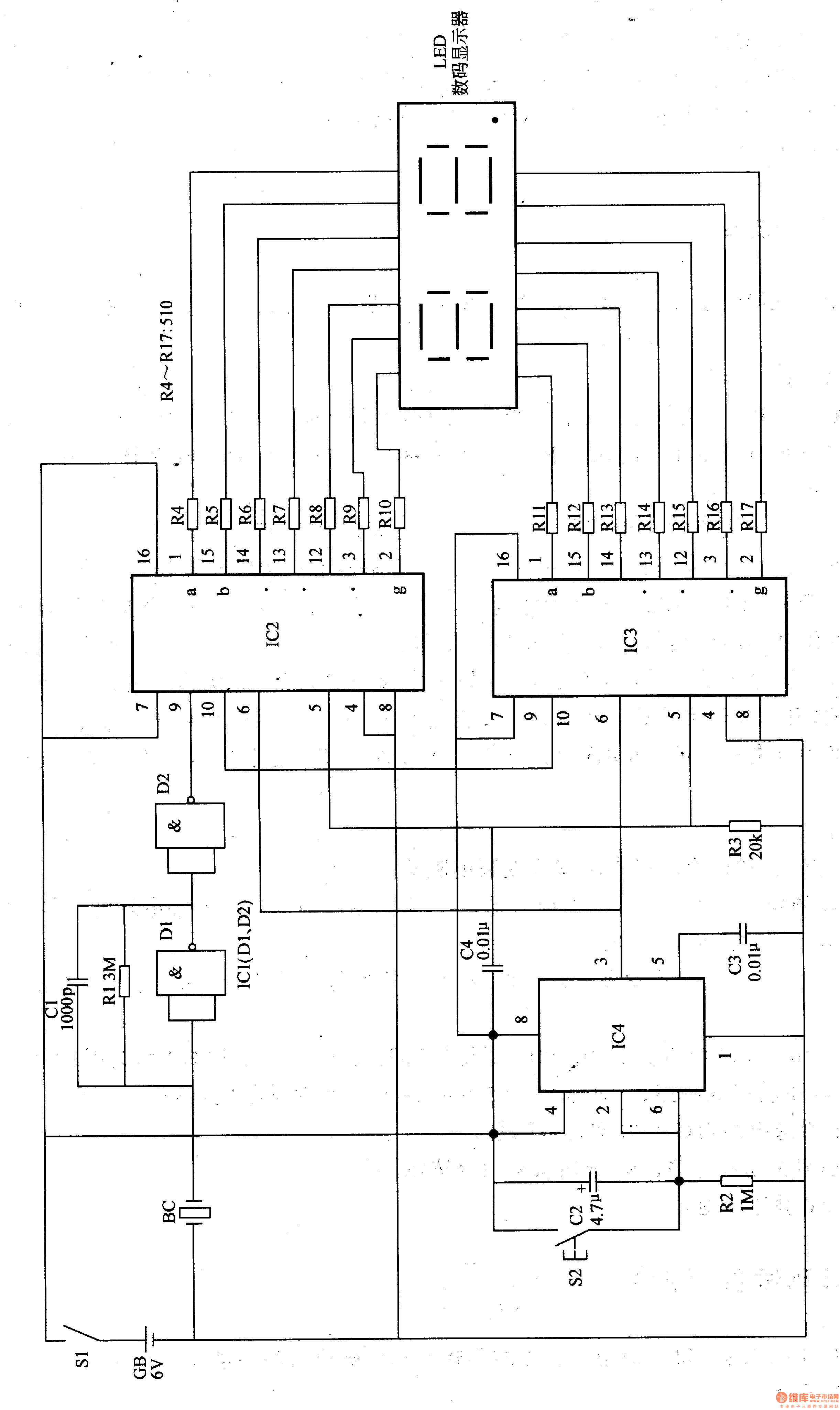
The circuit consists of pulse signal dealing circuit, timing circuit and display driving circuit. (It is showed in picture 9-50.)
Pulse signal dealing circuit consists of piezoelectric ceramics BC (as sensors), resistors Rl, capacitor Cl and NAND gate integrated circuit ICl (Dl, D2).
Timing circuit consists of reset button S2, capacitors C2-C4, resistor R2 and time-base integrated circuit IC4.
Display driving circuit consists of display driver integrated circuit IC2, 1C3, resistors R3-R17 and digital display.
When you turn on the power switch S1, IC2 and IC3 are minimum clearing. Put BC on the position where the pulse is significant. BC changes the pulse signal to electronic signal. Press S2 and C2 discharges quickly through S2. IC2 and IC3 start counting. The number which is displayed on the LED digital display is the jumping number of times of pulse per minute.
Reprinted Url Of This Article:
http://www.seekic.com/circuit_diagram/Signal_Processing/Pulse_Test_Set_the_3rd.html
Print this Page | Comments | Reading(3)

Article Categories
power supply circuit
Amplifier Circuit
Basic Circuit
LED and Light Circuit
Sensor Circuit
Signal Processing
Electrical Equipment Circuit
Control Circuit
Remote Control Circuit
A/D-D/A Converter Circuit
Audio Circuit
Measuring and Test Circuit
Communication Circuit
Computer-Related Circuit
555 Circuit
Automotive Circuit
Repairing Circuit
Code: