Signal Processing
Photoelectric Smoke Detector
Published:2013/9/26 20:22:00 Author:lynne | Keyword: Photoelectric Smoke Detector | From:SeekIC


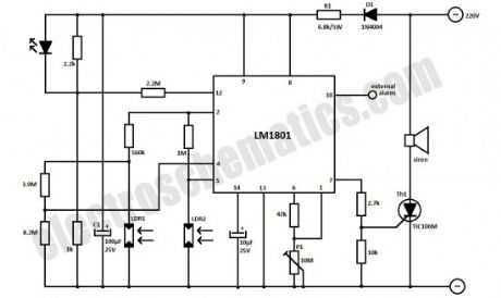
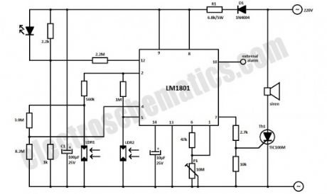
This photoelectric smoke detector circuit uses one LED and 2 LDRs to detect the smoke and sound an alarm. The LM1801 IC is the best choice for this circuit because we need a few external components and is used in almost any smoke alarm.
The whole photoelectric smoke detector circuit is powered from the 220V mains supply. D1 regulates the voltage, R1 decreases it until a proper level for the IC. C1 capacitor is filtering this voltage that is then stabilized with the zener diode inside LM1801.
Physically, the LDRs must be installed so that the smoke particles reflects the light from the LED on LDR2, causing decrease in its resistance. When there is smoke between the LED and LDRs the IC switches the thyristor Th1 which activates the siren.
The most difficult part in constructing this photoelectric smoke detector is to placement of LED and LDRs. Basically, the LED must be positioned exactly midway between the 2 LDRs, making sure there is no air flow between LED and LDR1. This can be accomplished by placing a transparent box around LDR1 and LED.The whole circuit sensitivity is adjustable with P1.
Reprinted Url Of This Article:
http://www.seekic.com/circuit_diagram/Signal_Processing/Photoelectric_Smoke_Detector.html
Print this Page | Comments | Reading(3)

Article Categories
power supply circuit
Amplifier Circuit
Basic Circuit
LED and Light Circuit
Sensor Circuit
Signal Processing
Electrical Equipment Circuit
Control Circuit
Remote Control Circuit
A/D-D/A Converter Circuit
Audio Circuit
Measuring and Test Circuit
Communication Circuit
Computer-Related Circuit
555 Circuit
Automotive Circuit
Repairing Circuit
Code: