Signal Processing
Photodiode_signal_conditonerfrepuency_output
Published:2009/7/24 3:36:00 Author:Jessie | From:SeekIC

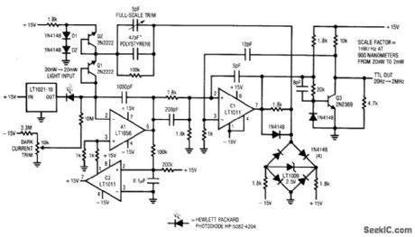
Fig. 14-9 This circuit converts a photodiode current output into an output frequency with 100 dB of dynamic range. Optical input power of 20 nW to 2 mW produces a linear 20-Hz to 2-MHz output. To calibrate the conditioner, place the photodiode in a completely dark environment and adjust the dark current trim so that the circuit oscillates at the lowest possible frequency, typically 1 or 2 Hz. Next, apply(or electrically simulate using the manufacturer's datasheet for light-input Versus output-current data)a 2-mW optical input. Adjust the full-scale trim capacitor for a 2-MHz output. If the adjustment is outside the range of the trimmer, alter the 47-pF value appropriately, Once calibrated, this circuit will maintain 1% accuracy(limited by the photodiode characteristics), Linear Technology Linea Applications Handbook 1990, p. AN7-9.
Reprinted Url Of This Article:
http://www.seekic.com/circuit_diagram/Signal_Processing/Photodiode_signal_conditonerfrepuency_output.html
Print this Page | Comments | Reading(3)

Article Categories
power supply circuit
Amplifier Circuit
Basic Circuit
LED and Light Circuit
Sensor Circuit
Signal Processing
Electrical Equipment Circuit
Control Circuit
Remote Control Circuit
A/D-D/A Converter Circuit
Audio Circuit
Measuring and Test Circuit
Communication Circuit
Computer-Related Circuit
555 Circuit
Automotive Circuit
Repairing Circuit
Code: