Signal Processing
Patient SOS Appliance One
Published:2011/7/17 1:00:00 Author:Felicity | Keyword: Patient SOS Appliance | From:SeekIC

Work of the circuit
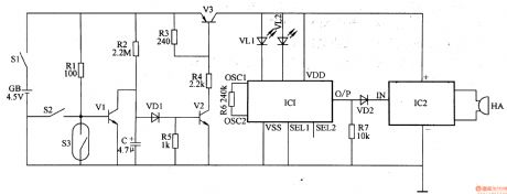
The circuit consists of SOS trigger circuit, sound and light alarm circuit and audio amplifier output circuit. (It is showed in picture 9-82.)
SOS trigger circuit consists of SOS switch S2, the trigger switch S3, the transistor Vl-V3, and the peripheral components.
Sound and light alarm circuit consists of audio integrated circuits ICl, resistors R6 and light-emitting diode VLl, VL2.
Audio amplifier output circuit consists of boost the audio power amplifier module IC2, super loudness piezoelectric buzzer HA, resistor R7 and diode VD2.
When the user is in the normal state, the power switch and calling switch is on, and the trigger switch S3 is off. V1 is saturated and on and V2 and V3 cut off. IC2 and IC3 are both off, and the beeper HA is noiseless. LED VL1 and VL2 are off. When the user is ill and fall down, S3 is on, and V1 cut off. V2 and V3 are on. IC1 and IC2 is power on and at work. The beeper HA sends out the whistle sound of ambulance and at the same time LED VL1 and VL2 are on and light the words ‘HELP’ and ‘Medicine is in the box’ on the first aid panel up.
Reprinted Url Of This Article:
http://www.seekic.com/circuit_diagram/Signal_Processing/Patient_SOS_Appliance_One.html
Print this Page | Comments | Reading(3)

Article Categories
power supply circuit
Amplifier Circuit
Basic Circuit
LED and Light Circuit
Sensor Circuit
Signal Processing
Electrical Equipment Circuit
Control Circuit
Remote Control Circuit
A/D-D/A Converter Circuit
Audio Circuit
Measuring and Test Circuit
Communication Circuit
Computer-Related Circuit
555 Circuit
Automotive Circuit
Repairing Circuit
Code: