Oscillator Circuit
Index 17
Fixed-amplitude RC phaser oscillator circuit diagram
Published:2011/9/2 1:34:00 Author:Ecco | Keyword: Fixed-amplitude RC, phaser oscillator
View full Circuit Diagram | Comments | Reading(1100)
Low-cost second signal oscillator circuit diagram
Published:2011/9/9 2:34:00 Author:Ecco | Keyword: second signal oscillator
View full Circuit Diagram | Comments | Reading(717)
Three-phase output oscillator circuit diagram
Published:2011/9/2 1:36:00 Author:Ecco | Keyword: Three-phase output , oscillator
View full Circuit Diagram | Comments | Reading(1324)
Oscillator connection circuit diagram
Published:2011/9/1 1:55:00 Author:Ecco | Keyword: Oscillator connection
View full Circuit Diagram | Comments | Reading(668)
Colpitts oscillator circuit diagram
Published:2011/8/18 1:22:00 Author:Jessie | Keyword: Colpitts oscillator
View full Circuit Diagram | Comments | Reading(1421)
High-frequency high-voltage oscillator(DC voltage convertor) circuit diagram
Published:2011/8/18 1:23:00 Author:Jessie | Keyword: High-frequency high-voltage oscillator, DC voltage convertor
View full Circuit Diagram | Comments | Reading(1276)
Electronic voltage regulated electromagnetic vibration circuit diagram
Published:2011/8/18 1:29:00 Author:Jessie | Keyword: Electronic voltage regulated, electromagnetic vibration
View full Circuit Diagram | Comments | Reading(1072)
Complementary tube free running multivibrator circuit diagram
Published:2011/8/18 1:47:00 Author:Jessie | Keyword: Complementary tube, free running, multivibrator
View full Circuit Diagram | Comments | Reading(974)
Multiple unit tube RC bridge oscillation circuit diagram
Published:2011/8/18 2:12:00 Author:Jessie | Keyword: multiple unit tube, bridge, oscillation
View full Circuit Diagram | Comments | Reading(919)
Common emitter inductance feedback oscillation circuit diagram
Published:2011/8/18 2:14:00 Author:Jessie | Keyword: common emitter, inductance feedback oscillation
View full Circuit Diagram | Comments | Reading(802)
Transformer oscillator(single tube) circuit diagram
Published:2011/8/25 1:40:00 Author:Ecco | Keyword: Transformer oscillator, single tube
View full Circuit Diagram | Comments | Reading(830)
Classic Cyle circuit
Published:2011/8/14 7:39:00 Author:leo | Keyword: Classic Cyle circuit
View full Circuit Diagram | Comments | Reading(656)
The oscillator formed by CC4066
Published:2011/8/14 5:48:00 Author:leo | Keyword: Oscillator

As the picture shows, this is an oscillator made by CMOS analog electronic switch CC4066. The circuit in the picture is formed by two electronic switches. The frequency of this oscillator is decided by resistance components. When the R1 =R2 and C1=C2, the circuit generates square wave and f=1/2RC. (View)
View full Circuit Diagram | Comments | Reading(1667)
Square wave oscillator(741)
Published:2011/8/14 7:06:00 Author:leo | Keyword: Square wave, oscillator

As the picture shows, this is an oscillator of square wave. It can generate the square wave with more than 100 to 1000 Hz frequency. Its frequency can be adjusted through resistor with 100kohms and 1Mohms. And the linearity of its output square wave is adjusted by resistor with 10kohms. If it only outputs at the same frequency, it can use fixed resistor to replace 100kohms and 1Mohms resistors. (View)
View full Circuit Diagram | Comments | Reading(1907)
Direct self-excited feedback astable multivibrator circuit composed of 555
Published:2011/8/15 22:23:00 Author:Ecco | Keyword: Direct self-excited feedback, astable multivibrator , 555
View full Circuit Diagram | Comments | Reading(628)
Venturi Bridge Oscillation Circuit of LM377
Published:2011/8/3 6:44:00 Author:Michel | Keyword: Venturi Bridge, Oscillation Circuit

The picture 1 is Venturi bridge oscillation circuit of LM377.In the circuit,VT1 is used to limit the amplitude of the oscillating circuit and C3 and C6 are isolation capacitances.C5 is used to prevent high frequency oscillation.The series loop circuit composed of R2 and C2 and parallel loop circuit composed of R1 and C1 constitute postive feedback circuit.It can determine the oscillation frequency of the circuit.R10,R4,R6 and VT1 constitute negative feedback circuit and decides the limiting amplitude of the circuit.
When it is 10 KHz,the circuit distortion rate is lower than 1% and the distortion rate can be improved via adjusting the resistance value.According to the circuit parameters,the effective output voltage is 7.5V when it is 60Hz. (View)
View full Circuit Diagram | Comments | Reading(1260)
1024KHz temperature compensation crystal oscillator circuit diagram
Published:2011/8/9 19:59:00 Author:Sophia | Keyword: 1024KHz temperature compensation, crystal oscillator

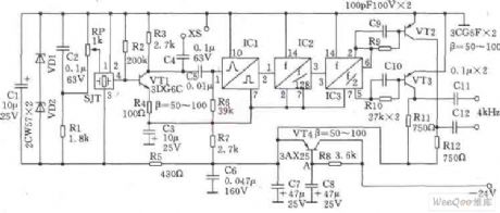
This circuit SJT is 1024kHz temperature compensation crystal oscillator. Circuit theoryis asshown. Because output signal level of the circuit is low, the buffer of follow-up transistor VTl is amplified. VTl base bias resistor R2, the load resistor R3, the emitter resistor R4 are the negative feedback resistors for stablizing VTl DC operating point. Zener diode VDl, VD2, capacitor Cl form stabilivolt and filter circuit to reduce the influency of the supply voltage fluctuations on the frequency of the crystal SJT. Resistors Rl and potentiometer RP TCXO provide bias voltage. regulation of RP can fine-tune the oscillator to reach precise frequency.
(View)
View full Circuit Diagram | Comments | Reading(1808)
74 Series digital circuit of 74LS326 dual VCO(two-way output with controlling)
Published:2011/8/9 3:29:00 Author:Lucas | Keyword: 74 Series , digital circuit , dual VCO, two-way output, controlling


There are two independent voltage-controlled oscillators; output frequency is determined by the external components; it can works at any frequency between 0.12Hz and 30MHZ; it has the complementary output and allowable input end.
(View)
View full Circuit Diagram | Comments | Reading(1167)
74 Series digital circuit of 74LS321 crystal-controlled oscillator
Published:2011/8/1 20:51:00 Author:Lucas | Keyword: 74 Series, digital circuit, crystal-controlled oscillator


It is similar to 74LS320, but there are two TTL-level outputs by counting F / 2 and F / 4.
(View)
View full Circuit Diagram | Comments | Reading(1075)
74 Series digital circuit of 74LS325 dual VCO(two-phase output)
Published:2011/8/1 20:34:00 Author:Lucas | Keyword: 74 Series, digital circuit , dual VCO, two-phase output

There are two independent voltage-controlled oscillators; output frequency is determined by the external components; it can works at any frequency between 0.12Hz and 30MHZ; it has the complementary output.
(View)
View full Circuit Diagram | Comments | Reading(1070)
| Pages:17/54 1234567891011121314151617181920Under 20 |
Circuit Categories
power supply circuit
Amplifier Circuit
Basic Circuit
LED and Light Circuit
Sensor Circuit
Signal Processing
Electrical Equipment Circuit
Control Circuit
Remote Control Circuit
A/D-D/A Converter Circuit
Audio Circuit
Measuring and Test Circuit
Communication Circuit
Computer-Related Circuit
555 Circuit
Automotive Circuit
Repairing Circuit


