Oscillator Circuit
THREE_FREQUENCY_AUDIO_OSCILLATOR
Published:2009/7/20 4:20:00 Author:Jessie | From:SeekIC

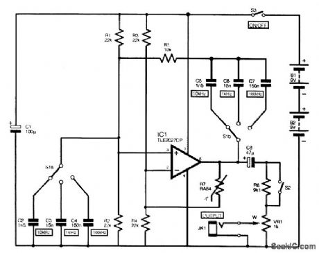
The full circuit diagram for the audio sine-wave generator is shown. Resistors R1 and R2 bias the noninverting (pin 3) input of IC1, and their parallel resistance forms one element of the Wien net-work. They are the equivalent of R1 in Fig. 1. The other resistor in the Wien network is R5. Three switched pairs of capacitors (C2 to C7) provide the unit with its three different output frequencies. Resistors R3 and R4 bias the inverting (pin 2) input of IC1, and their parallel resistance also acts as one element of the negative-feedback network. Thermistor R7 is the other section of the negative-feedback circuit. An RA53 thermistor is the normal choice for this application, but because of its lower cost, an RA54 is used in this circuit. Potentiometer VR1 is the variable-output attenuator. Opening switch S2 introduces losses through resistor R6 that reduce the output by about 20 dB. Use a value of 100 kΩ for R6 if a reduction by about 40 dB is preferred.
Reprinted Url Of This Article:
http://www.seekic.com/circuit_diagram/Signal_Processing/Oscillator_Circuit/THREE_FREQUENCY_AUDIO_OSCILLATOR.html
Print this Page | Comments | Reading(3)

Article Categories
power supply circuit
Amplifier Circuit
Basic Circuit
LED and Light Circuit
Sensor Circuit
Signal Processing
Electrical Equipment Circuit
Control Circuit
Remote Control Circuit
A/D-D/A Converter Circuit
Audio Circuit
Measuring and Test Circuit
Communication Circuit
Computer-Related Circuit
555 Circuit
Automotive Circuit
Repairing Circuit
Code: