Oscillator Circuit
SINUSOIDAL_3_Hz_TO_300_kHz_VCO
Published:2009/6/23 4:15:00 Author:May | From:SeekIC


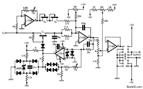
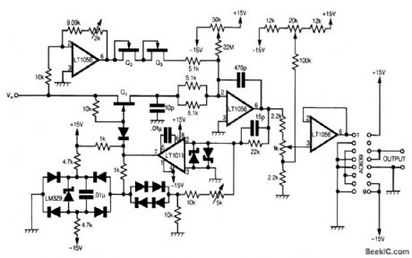
This circuit uses Analog Devices' AD639 universal trigonometric function generator to convert a triangle waveform, the basic waveform of the VCO itself, into a very low-distortion sine wave.By using the AD639 in its frequency tripler mode [2], the frequency range 3 Hz to 300 kHz is now covered. The circuit has been drawn here so that the oscillator loop, consisting of Q1, the integrator and the LT1011 comparator, is clearly shown.When Q1 is off, the input amplifier, which is adjusted to have a gain of exactly -1, pulls a current VIN/R, where R is 5.1 kΩ in series with two JFETs, and Q2 and Q3, out of the virtual earth of the in-tegrator. The output of the integrator thus rises at a rate of VIN/CR, where C = 470 pF. At a level that can be adjusted by the 5-kΩ potentiometer, the comparator flips and turns on Q1.A current of exactly 2VIN/R, is now supplied to the virtual earth of the integrator because there are now two 5.1-kΩ resistors in parallel and only a single JFET in between the virtual earth and Vin.The integrator output now falls at a rate of VIN/CR and the cycle repeats. Any offset in the current to the virtual earth of the integrator, due to circuit board leakage, etc., can be corrected by adjusting the 50-kΩ potentiometer. It follows that the symmetry of the triangle wave at the integrator output can be corrected by adjusting the 2-kΩ potentiometer, and the 50-kΩ potentiometer at VLF, and the frequency can be trimmed with the 5-kΩ potentiometer.The l-kΩ potentiometer variable is adjusted to give the input level to the AD639 needed to drive it over ±270°and so produce a sinusoidal output at three times the frequency of the triangle-wave input. Offset correction for the AD639 is made at the input to the voltage follower by means of the 20-kΩ potentiometer.Once a symmetric triangle wave has been obtained by adjusting the 2-kΩ and 50-kΩ poten-tiometers, and the correct frequency of 100 kHz has been set for VIN/=10 V, by adjusting the 5-kΩ potentiometer, the triple-frequency she-wave output can be set up by adjustment of the 1-kΩ and 20-kΩ potentiometers.This is best done by triggering the CRO from the triangle wave, and then viewing at least three complete cycles of output. Having adjusted for a clean-looking sine wave, the final adjustment of the 1-kΩ and 20-kΩ potentiometers should be made on a single sinusoidal cycle display, using internal trigger so that the three slightly different parts of the output cycle lie one upon the other and can be made to merge. Q1, Q2, and Q3 are 2N4391s, the two Schottlqr diodes are 5082-2810, and the other nine diodes are 1N914.All device power supply pins should be decoupled with 0.33 p.F. Resistors associated with the in-puts of the devices should be 1% high-stability parts.
Reprinted Url Of This Article:
http://www.seekic.com/circuit_diagram/Signal_Processing/Oscillator_Circuit/SINUSOIDAL_3_Hz_TO_300_kHz_VCO.html
Print this Page | Comments | Reading(3)

Article Categories
power supply circuit
Amplifier Circuit
Basic Circuit
LED and Light Circuit
Sensor Circuit
Signal Processing
Electrical Equipment Circuit
Control Circuit
Remote Control Circuit
A/D-D/A Converter Circuit
Audio Circuit
Measuring and Test Circuit
Communication Circuit
Computer-Related Circuit
555 Circuit
Automotive Circuit
Repairing Circuit
Code: