Oscillator Circuit
Dual D flip-flop VCO
Published:2011/4/18 20:14:00 Author:Ecco | Keyword: Dual D, flip-flop , VCO | From:SeekIC

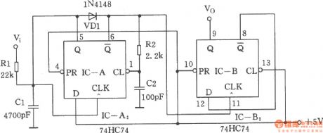
The chart shows the dual D flip-flop VCO. Circuit outputs a 50% duty cycle square wave signal, while the consumption of current is very low. When the input voltage is 5 ~ 12V, the output frequency ranges from 20 ~ 70kHz. First assuming the initial state of IC-A is Q = low level. At this time, VDl turns off, Vi charges to Cl through Rl. When the voltage on Cl reaches a certain voltage level, IC-A is forced to flip, its Q output is in high level, Cl discharges through VDl. At the same time, the CL input of IC-A will be transformed into low level, IC-A is forced back to Q = low level. The delay effect of R2 and C2 discharges the electricity of C1 before the IC-A returning to the state of Q = low level. The narrow pulse current of IC-A triggers IC-B, it produces a 50% duty cycle output pulse signal.
Reprinted Url Of This Article:
http://www.seekic.com/circuit_diagram/Signal_Processing/Oscillator_Circuit/Dual_D_flip_flop_VCO.html
Print this Page | Comments | Reading(3)

Article Categories
power supply circuit
Amplifier Circuit
Basic Circuit
LED and Light Circuit
Sensor Circuit
Signal Processing
Electrical Equipment Circuit
Control Circuit
Remote Control Circuit
A/D-D/A Converter Circuit
Audio Circuit
Measuring and Test Circuit
Communication Circuit
Computer-Related Circuit
555 Circuit
Automotive Circuit
Repairing Circuit
Code: