Signal Processing
MARKER_GENERATOR
Published:2009/7/7 7:50:00 Author:May | From:SeekIC

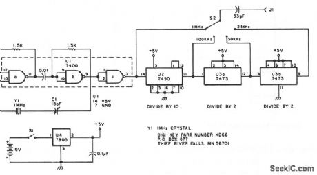
The oscillator section uses three sections of a 7400 quad NAND gate integrated circuit. The 1-MHz signal from the oscillator is fed into a 7490 decade counter configured to divide by ten, providing the 100-kHz signal. To obtain the 50 and 25 kHz outputs, the 100-kHz signal is further divided by 7473 dual J-K flip-flop. The first half of the 7473 divides the 100-kHz signal by two, yielding the 50 kHz signal. The second half of the 7473 again divides by two, giving the 25 kHz signal. S2 selects the output, a square wave, rich in harmonics. The generator can be powered from any convenient 6 to 12 Vdc source. A 7805 ftxed-voltage regulator supplies the regulated voltage for the oscillator and the divider chips. The generator described here is powered by a 9-V transistor radio battery.
Reprinted Url Of This Article:
http://www.seekic.com/circuit_diagram/Signal_Processing/MARKER_GENERATOR.html
Print this Page | Comments | Reading(3)

Article Categories
power supply circuit
Amplifier Circuit
Basic Circuit
LED and Light Circuit
Sensor Circuit
Signal Processing
Electrical Equipment Circuit
Control Circuit
Remote Control Circuit
A/D-D/A Converter Circuit
Audio Circuit
Measuring and Test Circuit
Communication Circuit
Computer-Related Circuit
555 Circuit
Automotive Circuit
Repairing Circuit
Code: