Signal Processing
Liquid_flowmeter_thermally_based
Published:2009/7/24 3:25:00 Author:Jessie | From:SeekIC

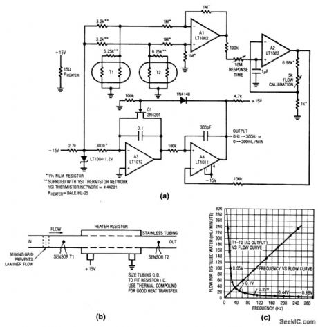
Fig. 14-3 This circuit shows a thermally based flowmeter, which features highly accurate rates as low as 1 mL/min and has a frequency output, which is a linear function of flow rate. This design measures the differential temperature between two sensors (Fig. 14-3B). Sensor T1, located before the heater resistor, assumes the fluid's temperature before the fluid is heated by the resistor. Sensor T2 picks up the temperature rise that is induced into the fluid by the resistor. The sensor difference signal appears at the Al output. A2 amplifies this difference with a time constant set by the response time adjustment. Figure 14-3C shows A2 output versus flow rate. The curves shown are for distilled water. To calibrate, set a flow rate of 10 mL/min and adjust the flow calibration trim for 10-Hz output. Linear Technology Linear Applications Handbook 1990 p AN5-6.
Reprinted Url Of This Article:
http://www.seekic.com/circuit_diagram/Signal_Processing/Liquid_flowmeter_thermally_based.html
Print this Page | Comments | Reading(3)

Article Categories
power supply circuit
Amplifier Circuit
Basic Circuit
LED and Light Circuit
Sensor Circuit
Signal Processing
Electrical Equipment Circuit
Control Circuit
Remote Control Circuit
A/D-D/A Converter Circuit
Audio Circuit
Measuring and Test Circuit
Communication Circuit
Computer-Related Circuit
555 Circuit
Automotive Circuit
Repairing Circuit
Code: