Signal Processing
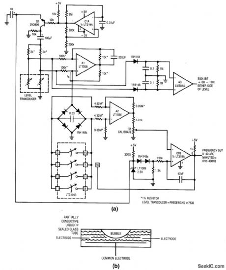
Level_transducer_digitizer
Published:2009/7/24 3:32:00 Author:Jessie | From:SeekIC

Fig.14-7 This circuit converts the angle(from an ideal level)to a corresponding frequency using a simple bubble-based transducer such as shown in Fig 14-7B.The circuit also provides a sign output(+ or -)to show either side of ideal level.If the transducer (bubble tube) is level with respect to gravity, the bubble is at the tube center and the electrode resistances to common are identical. As the tube shifts away from level, the resistances increase and decrease proportionally. By controlling the tube shape at manufacture, it is possible to get a linear output signal when the transducer is incorporated into a bridge circuit. To calibrate, place the level transducer at a known 40 arc-minute angle and adjust the calibrate potentiometer (at C1B) for a 400-Hz output. Circuit accuracy is limited by the transducer to about L5% Linear Technology Linear Applications Handbook l990, p. ANl7-12, -23.
Reprinted Url Of This Article:
http://www.seekic.com/circuit_diagram/Signal_Processing/Level_transducer_digitizer.html
Print this Page | Comments | Reading(3)

Article Categories
power supply circuit
Amplifier Circuit
Basic Circuit
LED and Light Circuit
Sensor Circuit
Signal Processing
Electrical Equipment Circuit
Control Circuit
Remote Control Circuit
A/D-D/A Converter Circuit
Audio Circuit
Measuring and Test Circuit
Communication Circuit
Computer-Related Circuit
555 Circuit
Automotive Circuit
Repairing Circuit
Code: