Signal Processing
LINEAR_SAWTOOTH_WAVEFORM_GENERATOR_CIRCUIT
Published:2009/7/13 22:20:00 Author:May | From:SeekIC

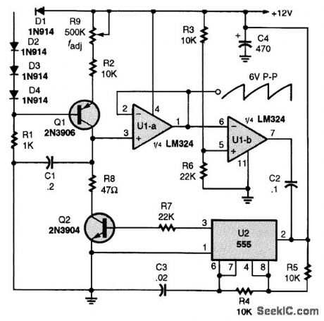
In this circuit, Q1 is a constant-current source, whose output is controlled by R9. C1 charges linearly, and follower U1-a drives comparator U1-b. When the threshold set by R3 and R6 is reached, U1-b changes state and triggers pulse generator U2, gating on Q2 and discharging C1 through R8.The cycle then repeats. The period is approximately 8 x C1/I1, where I1, is the collector current of Q1, as set by R9 and the base bias on Q1.
Reprinted Url Of This Article:
http://www.seekic.com/circuit_diagram/Signal_Processing/LINEAR_SAWTOOTH_WAVEFORM_GENERATOR_CIRCUIT.html
Print this Page | Comments | Reading(3)

Article Categories
power supply circuit
Amplifier Circuit
Basic Circuit
LED and Light Circuit
Sensor Circuit
Signal Processing
Electrical Equipment Circuit
Control Circuit
Remote Control Circuit
A/D-D/A Converter Circuit
Audio Circuit
Measuring and Test Circuit
Communication Circuit
Computer-Related Circuit
555 Circuit
Automotive Circuit
Repairing Circuit
Code: