Signal Processing
Humidity_to_frequency_converter
Published:2009/7/24 3:30:00 Author:Jessie | From:SeekIC

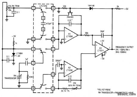
Fig. 14-6 This circuit converts the output of a relative-humidity (RH) transducer into a calibrated frequency output, using an LTC1043 switched-capacitor IC. To calibrate, place the transducer in a 5% RH environment, and adjust the 5% RH trim for 50-Hz output. Next, place the transducer in a 90% RH environment, and adjust the 90% RH trim for a 900-Hz output. Repeat this procedure unti1 both points are fixed. Relative humidity accuracy will be 2% over the 5%-90% RH range. If RH standards are not available, the circuit can be approximately calibrated with fixed capacitors in place of the transducer. Ideal values are 5% RH=379.3 pF and 90% = 523.8 pF. Note that these values assume an ideal sensor. An actual device can depart from the values by as much as 10%. Linear Technology Linea Applications Handbook 1990 p AN7-11.
Reprinted Url Of This Article:
http://www.seekic.com/circuit_diagram/Signal_Processing/Humidity_to_frequency_converter.html
Print this Page | Comments | Reading(3)

Article Categories
power supply circuit
Amplifier Circuit
Basic Circuit
LED and Light Circuit
Sensor Circuit
Signal Processing
Electrical Equipment Circuit
Control Circuit
Remote Control Circuit
A/D-D/A Converter Circuit
Audio Circuit
Measuring and Test Circuit
Communication Circuit
Computer-Related Circuit
555 Circuit
Automotive Circuit
Repairing Circuit
Code: