Signal Processing
Heart Rhythm Tester (the 2nd)
Published:2011/7/17 5:04:00 Author:Felicity | Keyword: Heart Rhythm Tester, the 2nd | From:SeekIC

Work of the circuit
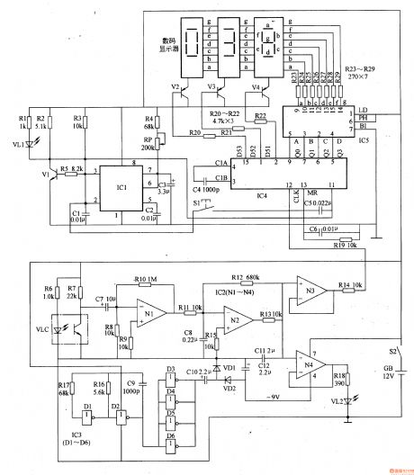
The circuit consists of infrared testing amplifying circuit, negative voltage producing circuit, working indicating circuit, timing circuit and digit displaying driving circuit. (It is showed in picture 9-54.)
Infrared testing amplifying circuit consists of infrared optocoupler (infrared sensor) VLC, resistors R6-Rl5, capacitors C7, C8, and Nl-N3 within the operational amplifier integrated circuit lC2 (Nl-N4).
Negative voltage producing circuit consists of six non-gate integrated circuit IC3 (Dl-D6), resistors Rl6, R17, capacitor Cg-C11 and diode VDl, VD2.
Working indicating circuit consists of capacitor Cll, IC2 internal op amp N4, resistors R18 and power indicator LED VL2.
Timing circuit consists of time-base integrated circuit rCl, resistors R1-R5, potentiometer RP, capacitors Cl-C3, light-emitting diodes VLl and transistors Vl.
Digit displaying driving circuit consists of digital displays, transistors V2-V4, resistors R2O-R29, capacitors C4-C6, counter display driver integrated circuit IC4and decoding circuit IC5.
Turn on power switch S2 and the battery GB will provide +l2V working voltage to ICl-IC5. Oscillating signal is shaped and rectified. It then provides -9V voltage to IC2.
When you do the test put your finger on the reflexing window of VLC. Infrared signal goes through the soft tissue and reflexes on phalanx. The infrared photosensitive transistor receives the signal and turns it into electronic signals. The digital displayer starts working and N4 drives VL2 flash. After the regular time (30s) is over, the counter stops working. Double of the figure on the displayer is the tester’s heart rhythm.
Reprinted Url Of This Article:
http://www.seekic.com/circuit_diagram/Signal_Processing/Heart_Rhythm_Tester_the_2nd.html
Print this Page | Comments | Reading(3)

Article Categories
power supply circuit
Amplifier Circuit
Basic Circuit
LED and Light Circuit
Sensor Circuit
Signal Processing
Electrical Equipment Circuit
Control Circuit
Remote Control Circuit
A/D-D/A Converter Circuit
Audio Circuit
Measuring and Test Circuit
Communication Circuit
Computer-Related Circuit
555 Circuit
Automotive Circuit
Repairing Circuit
Code: