Signal Processing
Heart Rhythm Tester (the 1st)
Published:2011/7/17 5:29:00 Author:Felicity | Keyword: Heart Rhythm Tester | From:SeekIC

Heart Rhythm Tester (the 1st)
Work of the circuit
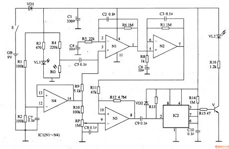
The circuit consists of blood flow runoff testing amplifying circuit, datum voltage circuit, comparing amplifying circuit, stable circuit, LED indicating circuit and power circuit. (It is shows in picture 9-53.)
Blood flow runoff testing amplifying circuit consists of resistor R3-R9, capacitor C2-C6, light-emitting diodes VLl, photosensitive resistor RG and Nl, N2 within the operational amplifier integrated circuit IC1 (Nl-N4).
Datum voltage circuit consists of resistors Rl, R2, R9, RlO, capacitor C7, IC1's internal operational amplifier N4and potentiometer RP.
Stable circuit consists of time-base integrated circuit IC2, diode VD2, capacitor C9, ClO, and resistors R13, R14.
LED indicating circuit consists of resistor Rl5, R16, transistors V and light emitting diodes VU.
When you do the test, put your finger on the testing sensor. The sensor consists of VL1 and RG. RG tests the signal voltage of the blood runoff. The signal is transited to N3 through N1 and N2. It produces positive impulse and negative impulse. It makes V work intermittently. It makes VL2 shines. The shining rate is the heart rhythm.
Change the value of RP to change the sensitivity of the circuit.
Reprinted Url Of This Article:
http://www.seekic.com/circuit_diagram/Signal_Processing/Heart_Rhythm_Tester_the_1st.html
Print this Page | Comments | Reading(3)

Article Categories
power supply circuit
Amplifier Circuit
Basic Circuit
LED and Light Circuit
Sensor Circuit
Signal Processing
Electrical Equipment Circuit
Control Circuit
Remote Control Circuit
A/D-D/A Converter Circuit
Audio Circuit
Measuring and Test Circuit
Communication Circuit
Computer-Related Circuit
555 Circuit
Automotive Circuit
Repairing Circuit
Code: