Signal Processing
Drunken Driving Limiter (the 3rd)
Published:2011/7/17 4:49:00 Author:Felicity | Keyword: Drunken Driving Limiter, the 3rd | From:SeekIC

Work of the circuit
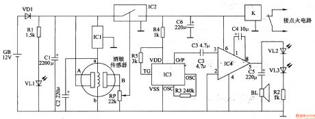
The circuit consists of power circuit, alcoholic testing circuit, sound circuit, sound amplifying and outputting circuit and igniting circuit. (It is showed in picture 7-162.)
Power circuit consists of battery GB, diode VDl, resistors Rl, power indicator LED VLl, filter capacitor Cl, C2, and three-terminal regulator integrator ICl.
Alcoholic testing circuit consists of wine-sensitive sensor, potentiometer and the electronic switch circuit IC2 RP.
Sound circuit consists of resistors R3-R5 and voice integrated circuits lC3.
Sound amplifying and outputting circuit consists of capacitor C3-C5, audio power amplifier integrated circuit IC4, speaker BL, LED Vl2 and VL3 and resistor R2.
Igniting circuit consists of capacitors C6 and relay K.
If the driver is drunk and wants to turn on S. IC1 tests the sense of alcohol. The electric resistance will become smaller. The electronic switch within IC1 is turned on. IC3 and IC4 starts to work. IC3 outputs the sound signal which is amplified by IC4. The signal drives BL make the sound that “Please do not drive when you are drunk.” VL2 and VL3 start shining. The power circuit of igniting circuit is cut off. The driver cannot start the car.
Reprinted Url Of This Article:
http://www.seekic.com/circuit_diagram/Signal_Processing/Drunken_Driving_Limiter_the_3rd.html
Print this Page | Comments | Reading(3)

Article Categories
power supply circuit
Amplifier Circuit
Basic Circuit
LED and Light Circuit
Sensor Circuit
Signal Processing
Electrical Equipment Circuit
Control Circuit
Remote Control Circuit
A/D-D/A Converter Circuit
Audio Circuit
Measuring and Test Circuit
Communication Circuit
Computer-Related Circuit
555 Circuit
Automotive Circuit
Repairing Circuit
Code: