Signal Processing
DIRECT_CONVERSION_WWV_RECEIVER
Published:2009/7/17 3:10:00 Author:Jessie | From:SeekIC

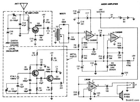
Incoming RF is picked by the antenna (ANTI) and is coupled via an autotransformer to a grounded-base amplifier (Q3) before being applied to a diode-mixer network that comprises T2, D1, and D2. The best mixer performance is obtained when both secondary windings of T2 are identical, and D1 and D2 are matched. The output of the local oscillator (LO)-a grounded-collector Colpitts oscillator (built around Q1)-is applied to emitter-follower/buffer Q2, which provides a low-impedance drive signal for the mixer. The demodulated signal is coupled to a pair of high-gain op-amp stages (U1-a and U1-b). The op amps provide a 50-dB gain. Amplifier U2 provides a 20-dB gain, thereby producing sufficient output drive for an 8-Ω speaker or 32-Ω headphones. The volume is controlled merely by adjusting the length of the whip antenna. When driving 32-Ω headphones, the circuit consumes less than 25 mA; however, the current drain increases to 40 mA when driving an 8-Ω speaker.
Reprinted Url Of This Article:
http://www.seekic.com/circuit_diagram/Signal_Processing/DIRECT_CONVERSION_WWV_RECEIVER.html
Print this Page | Comments | Reading(3)

Article Categories
power supply circuit
Amplifier Circuit
Basic Circuit
LED and Light Circuit
Sensor Circuit
Signal Processing
Electrical Equipment Circuit
Control Circuit
Remote Control Circuit
A/D-D/A Converter Circuit
Audio Circuit
Measuring and Test Circuit
Communication Circuit
Computer-Related Circuit
555 Circuit
Automotive Circuit
Repairing Circuit
Code: