Signal Processing
Bridge_oscillator_with_square_wave_output
Published:2009/7/24 5:33:00 Author:Jessie | From:SeekIC

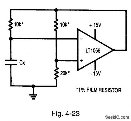
Figure 4-23 shows an oscillator circuit formed from the circuit of Fig. 4-22. In effect, the Fig. 4-23 circuit is a classic op-amp multivibrator (MV). The 10-kΩ/20-kΩ bridge leg provide switching-point hysteresis, with Cx charged through the remaining 10-kO resistor. When Cx reaches the switching point, the amplifier output changes state, abruptly reversing the sign of the positive output. The charging direction of Cx, also reverses to sustain oscillation. Output frequency depends on bridge components (at frequencies that are low compared to amplifier delays). Amplifier input errors tend to cancel, and supply shifts are generally rejected. The duty cycle is influenced by output saturation and supply asymmetry. LINEAR TECHNOLOGY, APPLICATION NOTE 43, P. 27.
Reprinted Url Of This Article:
http://www.seekic.com/circuit_diagram/Signal_Processing/Bridge_oscillator_with_square_wave_output.html
Print this Page | Comments | Reading(3)

Article Categories
power supply circuit
Amplifier Circuit
Basic Circuit
LED and Light Circuit
Sensor Circuit
Signal Processing
Electrical Equipment Circuit
Control Circuit
Remote Control Circuit
A/D-D/A Converter Circuit
Audio Circuit
Measuring and Test Circuit
Communication Circuit
Computer-Related Circuit
555 Circuit
Automotive Circuit
Repairing Circuit
Code: