Signal Processing
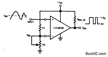
Basic_comparator
Published:2009/7/24 4:14:00 Author:Jessie | From:SeekIC

Fig. 15-1 This basic comparator circuit converts low-level analog signals to a high-level digital output. The pull-up resistor value should be high enough to avoid excessive power dissipation, yet low enough to supply sufficient drive to switch the load current at the comparator output. Resistors R1 and R2 set the input threshold trip voltage (VREF) at any value within the input common-mode range of the comparator. Notice that comparator common-mode characteristics are essentially the same as for op amps described in chapter 10. For example, with a VCC of 10 V, and both R1 and R2 at 5 kΩ, VREF can be set to any value up to 5V. National Semiconductor. Linear Applications Handbook, 1991, p. 257
Reprinted Url Of This Article:
http://www.seekic.com/circuit_diagram/Signal_Processing/Basic_comparator.html
Print this Page | Comments | Reading(3)

Article Categories
power supply circuit
Amplifier Circuit
Basic Circuit
LED and Light Circuit
Sensor Circuit
Signal Processing
Electrical Equipment Circuit
Control Circuit
Remote Control Circuit
A/D-D/A Converter Circuit
Audio Circuit
Measuring and Test Circuit
Communication Circuit
Computer-Related Circuit
555 Circuit
Automotive Circuit
Repairing Circuit
Code: