Signal Processing
ACCURATE_RAMP_GENERATOR
Published:2009/7/9 21:57:00 Author:May | From:SeekIC

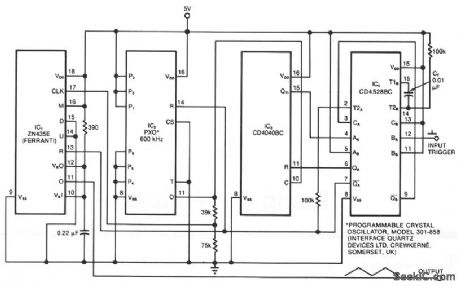
The ramp generator, an inexpensive alternative to commercial function generators, provides a more linear and repeatable output than conventional analog integrators. The circuit provides a triangle waveform in burst mode; in this case, two cycles of 10.24 ms each per input trigger pulse. IC4 is a dual monostable multi ibrator (one shot) in which the A side is configured as a latch (see Multivibrator IC performs extra tasks, EDN, September 6, 1984, p. 232). The rising edge of each input pulse triggers the B side, producing at pin 9 an output pulse whose duration depends on the timing capacitor's, CT, value-A 0.01-μF value gives a 500 μs pulse. This output provides a reset to the A side latch. While the latch is reset withQA, high, QA low, the other three ICs are active. The P1 through P6 connections, as shown, set oscillator IC2's frequency to 50 kHz at pin 11.Counter IC3 counts upward. The output at pin 11 of multifunction converter IC1 ramps up to fullscale, reverses, ramps down to zero, and then repeats this sequence of events. As this output completes its second cycle, IC3 reaches a count of 1024, causing the Q11 output to become high and toggle the IC4 latch. The resulting change of state on QA and QA resets the other three ICs, terminating further activity until the arrival of the next input trigger pulse. IC2 is included for its synchronous-reset capability, and it therefore drives the internal clock of IC1, which cannot be synchronously reset. Still IC2 can be omitted in some applications. The circuit operates from a 5-V supply. You can modify the output by changing IC2's frequency and IC3's output connection.
Reprinted Url Of This Article:
http://www.seekic.com/circuit_diagram/Signal_Processing/ACCURATE_RAMP_GENERATOR.html
Print this Page | Comments | Reading(3)

Article Categories
power supply circuit
Amplifier Circuit
Basic Circuit
LED and Light Circuit
Sensor Circuit
Signal Processing
Electrical Equipment Circuit
Control Circuit
Remote Control Circuit
A/D-D/A Converter Circuit
Audio Circuit
Measuring and Test Circuit
Communication Circuit
Computer-Related Circuit
555 Circuit
Automotive Circuit
Repairing Circuit
Code: