Signal Processing
800Hz signal generator
Published:2011/7/29 2:27:00 Author:Ecco | Keyword: 800Hz , signal generator | From:SeekIC

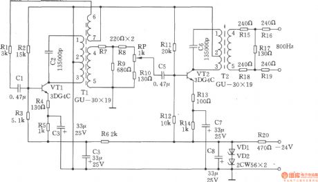
It is a LC oscillator circuit with800Hz oscillation level for the transformer coupled, it's a simple circuit, the frequency is stable. Buffer amplifier isused for reducing distortion, it can adjust the output level by potentiometer. 1. Specifications (1) operating frequency: 800Hz; (2) Frequency stability: ≤ ± 20Hz; (3) Output Level: 0dB/600Ω. 2.Working principle of the circuit is shown as the circuit. 800Hz signal generator is composed of LC oscillator and buffer amplifier. Oscillator: tuned transformer Tl is used as LC oscillation tank and output transformer, C2 is the tuned capacitor. The inductance of oscillation tank is the positive temperature coefficient, and polystyrene capacitor is the negative temperature coefficient, so the compensation of temperature coefficient improve the frequency stability. R2, R3 are DC bias resistors. R4, R5 are the emitter resistors of VTl, R4 has a current negative feedback. C3 is a bypass capacitor R5. R6 and R4 form a decoupling circuit for inter-stage power supply, R7, R8, R9 form the buffer attenuation device; buffer amplifier stage: C5 is the coupling capacitor, R11, Rl2 are bias resistors of VT2, Rl3, Rl4 are the emitter resistors of VT2, C7 is bypass capacitor of R14, C6 and T2 form a tuned output circuit to reduce distortion, RP potentiometer is used to adjust the output level. Buffer amplifier output terminal connecting to a 600Ω attenuation with Rl5 ~ Rl9 could provide 0dB output level. VDl, VD2, R20, C8 constitute regulator circuit.
Reprinted Url Of This Article:
http://www.seekic.com/circuit_diagram/Signal_Processing/800Hz_signal_generator.html
Print this Page | Comments | Reading(3)

Article Categories
power supply circuit
Amplifier Circuit
Basic Circuit
LED and Light Circuit
Sensor Circuit
Signal Processing
Electrical Equipment Circuit
Control Circuit
Remote Control Circuit
A/D-D/A Converter Circuit
Audio Circuit
Measuring and Test Circuit
Communication Circuit
Computer-Related Circuit
555 Circuit
Automotive Circuit
Repairing Circuit
Code: