Signal Processing
40_TO_43_MHz_VFO_CIRCUIT
Published:2009/7/22 3:59:00 Author:Jessie | From:SeekIC

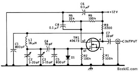
This is a recent 4.0- to 4.3-MHz oscillator design by KGBSU. It seems likely that performance could be improved by increasing the value of C2=C3 and decreasing that of L1 to make the device a true Vacker oscillator. The following component information is recommended by KGBSU: C1 and C5, 800-pF polystyrene; C2, air trimmer for setting calibration, C3, air variable for main tuning; C4, 70-pF, NPO ceramic and silver mica to provide required temperature compensation; C7, 33-pF NPO ce-ramic; C6 and C8, 0.1-μF 25-Vmonolithic capacitor; TR1, 40673 or SK3050 dual-gate MOSFET; D1, 1N4153 or 1N914 silicon signal diode; L1, 16-μF, 34 turns #26 enameled on 3/4-in diameter ceramic form (no slug core), winding length 0.6 inch; all resistors 0.25 W, 5 percent.
Reprinted Url Of This Article:
http://www.seekic.com/circuit_diagram/Signal_Processing/40_TO_43_MHz_VFO_CIRCUIT.html
Print this Page | Comments | Reading(3)

Article Categories
power supply circuit
Amplifier Circuit
Basic Circuit
LED and Light Circuit
Sensor Circuit
Signal Processing
Electrical Equipment Circuit
Control Circuit
Remote Control Circuit
A/D-D/A Converter Circuit
Audio Circuit
Measuring and Test Circuit
Communication Circuit
Computer-Related Circuit
555 Circuit
Automotive Circuit
Repairing Circuit
Code: