Signal Processing
300kHz Signal generator
Published:2011/4/21 5:32:00 Author:Ecco | Keyword: 300kHz , Signal generator | From:SeekIC

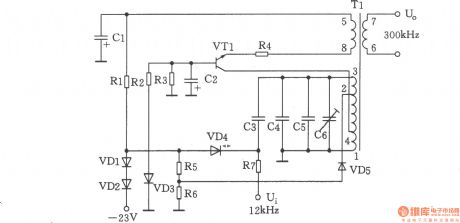
The chart shows the 300kHz signal generator. It is a voltage-controlled oscillator which is composed of VT1, T1, VD4 and related components. VCO use LC tuned collector, VTl is the oscillating tube, the 1 to 3 inductor winding of varactor diode VD4, and the capacitors C3 ~ C6 and transformer T1 form a tuning loop, the back biased work of varactor diode VD4 can control voltage which is applied to the negative side, and it can change its electrical capacity. The oscillating signal is from the output windings 6 to 7 of Tl. And C6 is the frequency tuning capacitor. VD3 stablizes oscillation voltage level, stable voltage is 6.8V ± 0.2V. Selection of components: transistor VT1: 3DG6C, β = 65 ~ 85. Diode VD1, VD2: 2CPl4, VD5: 2CK18. Zener diode VD3: 2CWl4. Varactor diode VD4: 2CC5. Resistor R1: 3.6k, R2: 3.3k, R3: 5.1k, R4: 510Ω, R5: 3.9k, R6: 3k, R7: 100k, the models are RTX-0.125W. Capacitors Cl, C2: 5μF30V, C3: 51pFl00V, C4: 820pFl00V, C5: (matching when measuring), C6: 20pF. Variable device T1: model L22, A = 100. L1-4: Φ0.29mm, around 27 turns, L2-3: Φ0.29mm, turn around l8, L4-2: Φ0.29ram with 9 turns, L5-8: Φ0.29mm with 7 turns, L6- 7: ΦO. 29mm with 6 turns. L1-3 = 292μH, allowable error range: 0 ~ 10μH.
Reprinted Url Of This Article:
http://www.seekic.com/circuit_diagram/Signal_Processing/300kHz_Signal_generator.html
Print this Page | Comments | Reading(3)

Article Categories
power supply circuit
Amplifier Circuit
Basic Circuit
LED and Light Circuit
Sensor Circuit
Signal Processing
Electrical Equipment Circuit
Control Circuit
Remote Control Circuit
A/D-D/A Converter Circuit
Audio Circuit
Measuring and Test Circuit
Communication Circuit
Computer-Related Circuit
555 Circuit
Automotive Circuit
Repairing Circuit
Code: