Signal Processing
18_2_MHz_FRONT_END
Published:2009/7/16 3:15:00 Author:Jessie | From:SeekIC

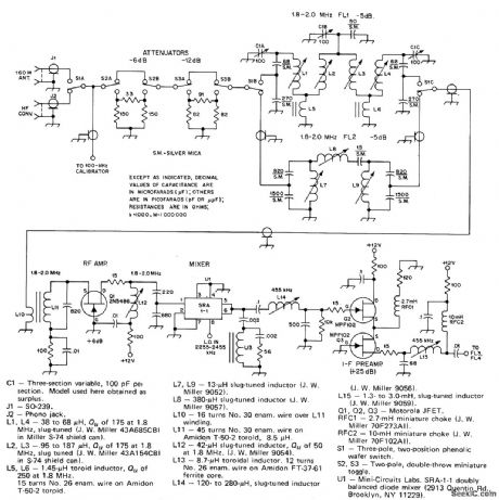
Includes enough attenuation for comfortable listening even when nearby high-power amateur station comes on air. Used with downconverter to cover 80 meters through 10 meters. Fixed-tuned 1.8-2 MHz bandpass filter FL2 eliminates need for repeaking three-pole tracking filter FL1 when tuning in band. RF amplifier Q1 compensates for filter loss by giving maximum of 6-dB gain. Double-balanced diode-ring mixer U1 handles high signal levels and has good port-to-port signal isolation. High-pass diplexer network at output of IC mixer U1 improve noise performance without degrading 455-kHz IF. Output goes to IF filter. Two-part article all other circuits of receiver. -D. DeMaw, His Eminence-the Receiver, QST, Part 1- June 1976, p27-30 (Part 2-July 1976, p 14-17).
Reprinted Url Of This Article:
http://www.seekic.com/circuit_diagram/Signal_Processing/18_2_MHz_FRONT_END.html
Print this Page | Comments | Reading(3)

Article Categories
power supply circuit
Amplifier Circuit
Basic Circuit
LED and Light Circuit
Sensor Circuit
Signal Processing
Electrical Equipment Circuit
Control Circuit
Remote Control Circuit
A/D-D/A Converter Circuit
Audio Circuit
Measuring and Test Circuit
Communication Circuit
Computer-Related Circuit
555 Circuit
Automotive Circuit
Repairing Circuit
Code: