Signal Processing
136 kHz direct conversion receiver
Published:2012/11/23 0:54:00 Author:muriel | Keyword: 136 kHz, direct conversion, receiver | From:SeekIC

1. Introduction
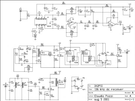
I describe a simple direct conversion receiver, thinked for QRSS and DFCW communications, as companion of ARGO or SPECTRAN programs. I don't pretend to beat the performances of professional or commercial ham radio receiver, the scope is to suggest an easy way for beginner to listen (of course I mean look at) the signals in this poorly populated band. The receiver is useful also as portable receiver, fast turn-on receiver for a quick look an the band or as very low cost (and performances) spectrum analyzer. I currently use this equipment for tests purposes (e.g. visual frequency meter etc.).
2. Circuit description
The front end is described elsewhere prea136.htm The scope is reduce as most as possible the image frequency. I have also tried a different front end, based on a low pass filter with frequency cut-off of 180 kHz. In my QTH I had a lot of undesirables signals on the screen of the PC. The filter is tuned with a signal generator for a bandwidth of 300 Hz, centered on 136.650 kHz. The coupling capacitor between the coils is also tuned for the desired bandwidth. The mixer is the well known NE602. It's not a monster of performances but it provides some gain, it's cheap and easy to find. The rest of audio amplifier is common to other direct conversion receiver. The local oscillator is the original part of my project. The frequency is fixed at 135.500 kHz, so that the image frequency for QRSS portion of the band (137.600 - 137.800 kHz)drop about 4 kHz lower. This permitted to attenuate the image using a simple front end filter. The oscillator is controlled by a 27.100 MHz crystal, the frequency is divided by 200 and the square wave is injected into the mixer. Adjust the trimmer V1 for the best signal to noise ratio (or the best sensitivity). CV1 is tuned for a secure start of oscillations, tune CV2 for the exact frequency of 27.100 MHz. The transformer T1 is winded on an Amidon T50-5 toroidal core. 19 turn primary, 4 turn secondary. There is not an audio amplifier, the output must be connected to the audio board of the computer. If you prefer an audio feedback use an IC amplifier (e.g. an LM386). I usually set-up ARGO offset frequency to read the actual frequency on the screen of the PC. I suggest to use a low noise operational amplifier as U2.
3. Performances
The stability is good since the drifts of the xtal oscillator are divided by 200. The sensitivity is also good since the natural and artificial noise on the band is high. The high selectivity filter in the front end reduce the possibility of overloading of the mixer. In my station the receiver is connected to the antenna through the low pass filter of the transmitter, helping in reducing overload from broadcasting stations. I think that a tuned loop antenna is the optimal companion for this receiver.
Reprinted Url Of This Article:
http://www.seekic.com/circuit_diagram/Signal_Processing/136_kHz_direct_conversion_receiver.html
Print this Page | Comments | Reading(3)

Article Categories
power supply circuit
Amplifier Circuit
Basic Circuit
LED and Light Circuit
Sensor Circuit
Signal Processing
Electrical Equipment Circuit
Control Circuit
Remote Control Circuit
A/D-D/A Converter Circuit
Audio Circuit
Measuring and Test Circuit
Communication Circuit
Computer-Related Circuit
555 Circuit
Automotive Circuit
Repairing Circuit
Code: