Sensor Circuit
Water Switch Sensor Circuit
Published:2012/9/24 22:25:00 Author:muriel | Keyword: Water,Switch,Sensor | From:SeekIC

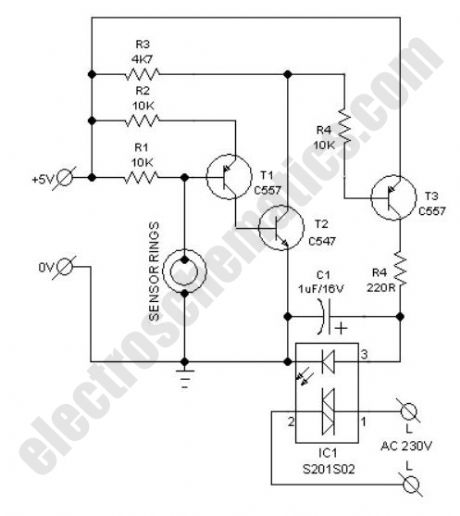
Possible applications for this water switch circuit: rain alarm, watertap leak detector, water level sensor for bathroom water heaters, wetness checker for flower pots and more. This circuit is nothing but a water activated solid-state switch (S201S02) capable of driving ac mains operated loads.How does the water switch circuit worksWorking principle of this circuit is very simple. When the sensor rings are bridged by water, an isolated electric switch turns on to activate the load (an alarm, for instance) connected through its switching contacts. Here, the renowned S201S02 solid-state relay (IC1) is wired as the electronic switch. Any low current 5VDC power unit can be used to feed input supply to the whole circuit.As clearly indicated in the circuit diagram, two closely spaced metal rings are used as the water sensor mechanism. However, one can use two metal needles/injection needles to make the sensor.
Water Switch Circuit Schematic
Reprinted Url Of This Article:
http://www.seekic.com/circuit_diagram/Sensor_Circuit/Water_Switch_Sensor_Circuit.html
Print this Page | Comments | Reading(3)

Article Categories
power supply circuit
Amplifier Circuit
Basic Circuit
LED and Light Circuit
Sensor Circuit
Signal Processing
Electrical Equipment Circuit
Control Circuit
Remote Control Circuit
A/D-D/A Converter Circuit
Audio Circuit
Measuring and Test Circuit
Communication Circuit
Computer-Related Circuit
555 Circuit
Automotive Circuit
Repairing Circuit
Code: