Sensor Circuit
WIND_DIRECTION_SENSOR
Published:2009/7/15 0:11:00 Author:Jessie | From:SeekIC


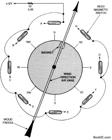
To use the circuit you will need a wind vane like the one shown. It should have a weighted front end and an air paddle in the rear. Attach a small, strong magnet to the front part of the wind-vane arm. Then, position eight reed magnetic switches in a circle around a piece of plastic pipe and electrically connect them (as shown). Note that the reed switches are electrically connected to points labeled A through H. Those points correspond to points A through H in the wind-direction decoder circuit. The decoder uses eight low-current 2N5061 SCRs and eight LEDs to latch and display the wind vane's position. If the wind vane is pointing due north, reed switch A is closed, sending current into the gate of SCR1. That current turns the thyristor on, causing it to light LED1. If the wind shifts slightly to a position in between north and northwest or north and northeast, without activating any of the reed switches, LED1 will remain on, indicating that the last wind direction was north. With SCR1 turned on, one end of capacitors C8 and C1 is pulled to ground. The other end of both capacitors is tied to the + 12-V bus through a resistor and LED; that means that both capacitors are charged to near 12 V. All other capacitors are not charged because both ends of each capacitor are returned to the +12-V bus through a resistor and LED. When the wind direction shifts to the northwest, reed switch B turns SCR2 on, thereby taking the positive end of C1, which is connected to its anode, to ground. This negative pulse turns SCR1 off as SCR2 turns on, lighting LED2 and turning off LED1.
Reprinted Url Of This Article:
http://www.seekic.com/circuit_diagram/Sensor_Circuit/WIND_DIRECTION_SENSOR.html
Print this Page | Comments | Reading(3)

Article Categories
power supply circuit
Amplifier Circuit
Basic Circuit
LED and Light Circuit
Sensor Circuit
Signal Processing
Electrical Equipment Circuit
Control Circuit
Remote Control Circuit
A/D-D/A Converter Circuit
Audio Circuit
Measuring and Test Circuit
Communication Circuit
Computer-Related Circuit
555 Circuit
Automotive Circuit
Repairing Circuit
Code: