Sensor Circuit
WATER_LEVEL_SENSING_AND_CONTROL
Published:2009/7/1 1:06:00 Author:May | From:SeekIC

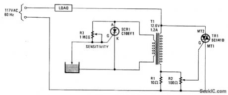
The operation of the circuit is based on the difference in the primary impedance of a transformer when its secondary is loaded and when it is open-circuit. The impedance of the primary of T1 and resistor R1 are in series with the load. The triac's gate-control voltage is developed across parallel resistors R1 and R2. When the water level is low, the probe is out of the water and SCR1 is triggered on. It conducts and imposes a heavy load on transformer T1's secondary winding. That load is reflected back into the primary, gating triac TR1 on, which energizes the load. If the load is an electric value in the water-supply line, it will open and remain open until the water rises and touches the probe, which shorts SCRl's gate and cathode, thereby turning off the SCR1, which effectively open-circuits the secondary. The open-circuit condition-when reflected back to the primary winding-removes the triac's trigger signal, thereby turning the water off. The load may range from a water valve, a relay controlling a pump supplying water for irrigation, or a solenoid valve controlling the water level in a garden lily pond.
Reprinted Url Of This Article:
http://www.seekic.com/circuit_diagram/Sensor_Circuit/WATER_LEVEL_SENSING_AND_CONTROL.html
Print this Page | Comments | Reading(3)

Article Categories
power supply circuit
Amplifier Circuit
Basic Circuit
LED and Light Circuit
Sensor Circuit
Signal Processing
Electrical Equipment Circuit
Control Circuit
Remote Control Circuit
A/D-D/A Converter Circuit
Audio Circuit
Measuring and Test Circuit
Communication Circuit
Computer-Related Circuit
555 Circuit
Automotive Circuit
Repairing Circuit
Code: