Sensor Circuit
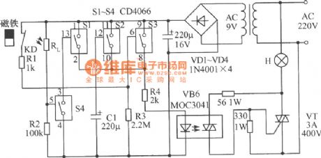
The auto light control circuit of photoelectric couplers
Published:2011/6/10 8:31:00 Author:qqtang | Keyword: control circuit, photoelectric couplers | From:SeekIC

See as the circuit, in the 4 teams of analog electric switches(SI~S4), S1, S2 and S3 are in parallel connection, and they are used in the time delaying circuit, when they are connected with the power supply, they drive the dual-way transistor VT by R4 and VB6, VT directly control the hall lights; S4 and the external light dependent resistor RL form the outside ray detection circuit. When the door is closed, the closed type dry reed pipe KD, which is installed on the door frame, is affected by the magnet and it cut off, then S1, S2 and S3 are in open state. When the owner comes home at night, the magnet is away from KD, the KD touch spot is closed.
Reprinted Url Of This Article:
http://www.seekic.com/circuit_diagram/Sensor_Circuit/The_auto_light_control_circuit_of_photoelectric_couplers.html
Print this Page | Comments | Reading(3)

Article Categories
power supply circuit
Amplifier Circuit
Basic Circuit
LED and Light Circuit
Sensor Circuit
Signal Processing
Electrical Equipment Circuit
Control Circuit
Remote Control Circuit
A/D-D/A Converter Circuit
Audio Circuit
Measuring and Test Circuit
Communication Circuit
Computer-Related Circuit
555 Circuit
Automotive Circuit
Repairing Circuit
Code: