Sensor Circuit
Sensor and Relay Circuits
Published:2012/10/25 21:29:00 Author:muriel | Keyword: Sensor , Relay Circuits | From:SeekIC

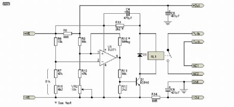
In Figure, I have shown the reed relay connections, together with an efficiency circuit (R13 & C4), that will reduce the holding current to the bare minimum. C4 is used to provide an initial full voltage to the relay coil, to ensure that it will pull in reliably. After C4 is charged, the only current flows through R13, and the current is just sufficient to keep the relay energised, so current drain is minimised. You may need to adjust the value of R13 depending on the relays used - as shown, it is suitable for a 12V reed relay with a coil resistance of around 1k ohm, and limits holding current to approximately 7.5mA. R16 is optional but recommended. It ensures that switching is clean , with no relay chattering. The series combination of R7 and R15 can be replaced with a single 51k resistor if preferred.
The sensor works by detecting the voltage dropped across the sense resistor. When current is drawn, a small voltage is developed across the resistor (R8), and this is used to switch the opamp from a normally high output state to a voltage of about 2V. This switches off Q1, which in turn de-activates the relay and disconnects the charger. When the external circuit is switched off, the voltage across the sense resistor falls to near zero, the opamp changes output state, and the relays are energised, thus reconnecting the charger.
The charger must be able to supply enough current to keep the relays energised, as well as provide power to charge the batteries (and power U1 - typically about 2.5mA), so minimising relay current is important.
If you switch the power to your external equipment on-off-on-off quickly, you may find that the relay does not re-activate after the last power-off. This can happen if C4 is charged, and has not had time to discharge fully, so the relay coil doesn't get the pulse needed to close the contacts. The easy way to prevent this is not to switch on and off rapidly.
Reprinted Url Of This Article:
http://www.seekic.com/circuit_diagram/Sensor_Circuit/Sensor_and_Relay_Circuits.html
Print this Page | Comments | Reading(3)

Article Categories
power supply circuit
Amplifier Circuit
Basic Circuit
LED and Light Circuit
Sensor Circuit
Signal Processing
Electrical Equipment Circuit
Control Circuit
Remote Control Circuit
A/D-D/A Converter Circuit
Audio Circuit
Measuring and Test Circuit
Communication Circuit
Computer-Related Circuit
555 Circuit
Automotive Circuit
Repairing Circuit
Code: