Magnetic Sensor
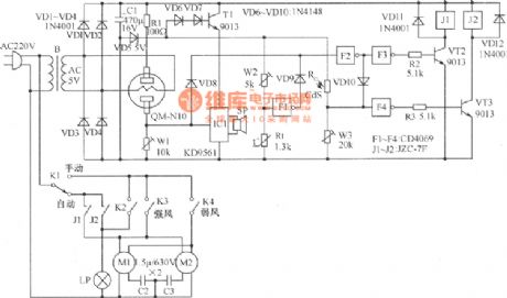
lampblack absorber automatic control circuit
Published:2011/8/16 2:10:00 Author: | Keyword: lampblack absorber, automatic control | From:SeekIC

The working principle:the gas sensor and W1 in the picture form the gas detection circuit,and the 5V AC power of power transformer will heat the heating silk of the gas sensor. Inverter F1, W2, thermistor Rt form the temperature sensing circuit.The high potential signal output by two detection circuit will control the motor control circuit formed by F2, F3, R2, VT2, J1 through the isolative diode VD8, VD9 respectively. Photosensitive resistor CdS, W3, F4, R3, VT3, J2 form the lighting control circuit; IC1 is the music alarm circuit, and it is controlled by the gas detection circuit.
Reprinted Url Of This Article:
http://www.seekic.com/circuit_diagram/Sensor_Circuit/Magnetic_Sensor/lampblack_absorber_automatic_control_circuit.html
Print this Page | Comments | Reading(3)

Article Categories
power supply circuit
Amplifier Circuit
Basic Circuit
LED and Light Circuit
Sensor Circuit
Signal Processing
Electrical Equipment Circuit
Control Circuit
Remote Control Circuit
A/D-D/A Converter Circuit
Audio Circuit
Measuring and Test Circuit
Communication Circuit
Computer-Related Circuit
555 Circuit
Automotive Circuit
Repairing Circuit
Code: